Selecting a 125amp Mccb is not a simple matter of matching amperage. The device must suit the available fault current, voltage, load profile, enclosure, and installation environment. A neat rating can still hide a poor selection.
The International Energy Agency’s Electricity 2024 report expects global electricity demand to grow by an average of 3.4% annually from 2024 through 2026. More demand means greater pressure on distribution equipment. Meanwhile, IEC 60947-2 defines important requirements for low-voltage circuit breakers, including operating performance and short-circuit protection. NFPA 70 also requires careful attention to conductor sizing, overcurrent protection, and installation conditions. These references provide a technical starting point, not a shortcut.
Jim Phillips, P.E., a recognized electrical safety educator, offers a practical warning: “The label is not the analysis.” That principle matters when choosing a 125amp Mccb. The same breaker may perform differently in a hot panel, a dusty factory, or a system with high prospective fault current. This guide examines seven selection points, including interrupting capacity, trip characteristics, pole configuration, thermal limits, and certification. It also considers a common weakness: catalogue data may look complete, while site measurements remain missing. Check the actual load. Confirm the fault level. Verify coordination with upstream and downstream devices. A qualified engineer should review the final choice before energization.
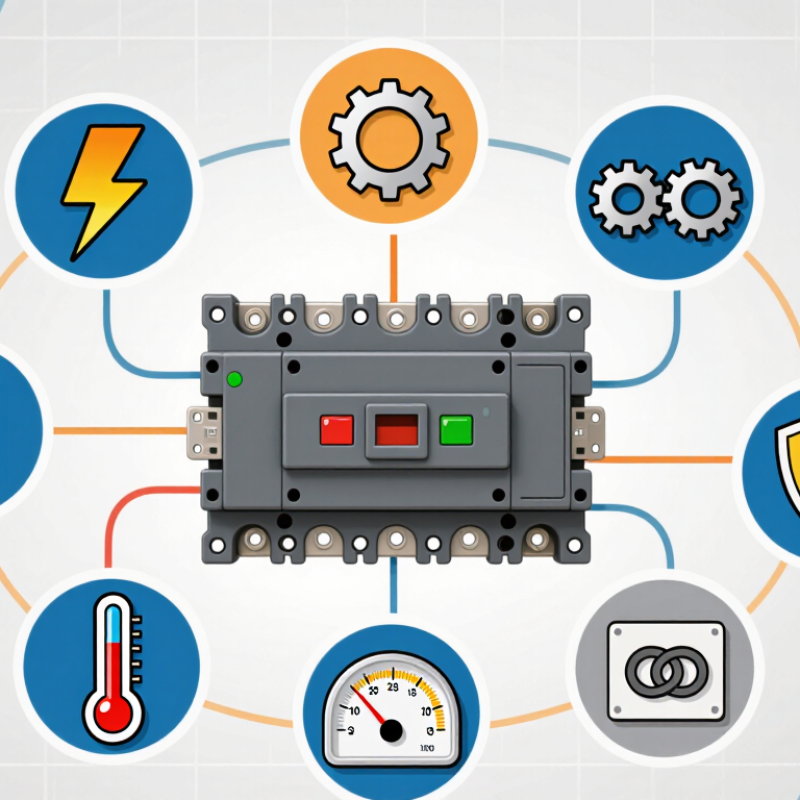
A 125 amp MCCB must carry the intended current without creating a weak point in the circuit. Confirm the 125 amp rating on the nameplate, not only in the product listing. Read the label carefully. Check the system voltage, frequency, number of poles, and connection arrangement. The breaker must match the circuit’s phase configuration and distribution equipment. A 125 amp rating alone does not prove compatibility.
Review the interrupting capacity against the available fault current at the installation point. This detail is critical near transformers or large electrical panels. Verify conductor size, insulation temperature, terminal limits, and the enclosure’s operating conditions. Continuous loads may require additional capacity under applicable electrical rules. A qualified electrician should confirm these calculations and local requirements. In field inspections, I have seen installers focus on amperage while overlooking voltage or terminal compatibility. That mistake is easy to make. It can cause overheating, nuisance trips, or unsafe protection. I once treated a catalog match as sufficient, then found the mounting arrangement was wrong. The lesson was uncomfortable but useful: check every interface before purchase. Also inspect ambient temperature and available space, since heat and poor ventilation can affect breaker performance. Keep the documentation with the panel for future testing and maintenance.
Tip 1: Match voltage before checking price. A 125 amp MCCB must suit the system’s nominal voltage and available fault current. IEC 60947-2 requires the breaker’s rated short-circuit capacity to meet installation conditions. A 480-volt device is not automatically suitable for a 208-volt panel. The connection design still matters.
Tip 2: Count poles from the circuit arrangement. A three-phase, three-wire feeder commonly uses three poles. A three-phase, four-wire system may require neutral switching, depending on the grounding method and local rules. NFPA 70, 2023, provides requirements for grounded conductors and disconnecting means. Do not assume a four-pole breaker is always safer. It can create coordination problems.
Tip 3: Check the complete system configuration. Confirm line-to-line voltage, phase sequence, neutral treatment, enclosure type, and upstream protection. The National Electrical Manufacturers Association’s AB 4 guidance emphasizes correct MCCB inspection, installation, and testing. Field conditions can differ from drawings. I still recheck them.
A 125 amp rating does not prove adequate protection. Continuous loads may require conductor and breaker sizing at 125 percent under applicable electrical codes. Verify terminal temperature ratings, conductor material, and tightening torque. A small mismatch can produce heat at the lug. That detail is easy to overlook. Use the manufacturer’s tested configuration, but evaluate it against the project’s actual fault level and maintenance conditions. According to the International Energy Agency’s Electricity 2024 report, global electricity demand is rising rapidly, making reliable distribution design more important. The report does not choose the breaker for you. Engineers must.
| Tip | Selection Dimension | Typical Data for a 125 Amp MCCB | How to Evaluate the Requirement | Important Verification |
|---|---|---|---|---|
| 1 | Verify the System Voltage | 120/240 V 208Y/120 V 480Y/277 V 600/347 V | Select an MCCB with a voltage rating equal to or higher than the system voltage. For three-phase systems, confirm both the line-to-line and line-to-neutral voltage where applicable. | Confirm the marked maximum operating voltage, frequency, and whether the device is approved for the specific AC system configuration. |
| 2 | Choose the Correct Number of Poles | 2-pole 3-pole 4-pole | Use 2-pole protection for single-phase line-to-line circuits, 3-pole protection for most three-phase three-wire circuits, and 4-pole protection when the neutral must be switched or isolated. | Determine whether the neutral is grounded, switched, or unswitched. A four-pole device may be required for certain systems, transfer equipment, or isolation procedures. |
| 3 | Match the System Configuration | Single-phase Three-phase, 3-wire Three-phase, 4-wire Grounded neutral | Identify the supply arrangement before selecting the breaker. A 3-pole MCCB is commonly used on three-phase three-wire circuits, while a 4-pole MCCB can provide neutral switching in a four-wire system. | Review the one-line diagram, grounding method, neutral arrangement, and any generator or transfer-switch connection. |
| 4 | Check Interrupting Capacity | 10 kA 25 kA 35 kA 50 kA+ | The breaker’s interrupting rating must be at least equal to the available prospective short-circuit current at the installation point. Higher fault levels require a higher-rated MCCB or an approved current-limiting solution. | Use the site short-circuit study or utility fault-current data. Verify the rating at the actual system voltage, not only the maximum rating listed for another voltage. |
| 5 | Select the Trip Unit and Protection Settings | Thermal-magnetic Electronic Fixed trip Adjustable trip | A thermal-magnetic trip unit is suitable for many general-purpose feeders. An electronic trip unit offers more precise long-time, short-time, instantaneous, and sometimes ground-fault settings. | Coordinate long-time pickup with the load and conductor ampacity. Confirm that short-circuit and ground-fault settings do not compromise downstream selectivity or equipment protection. |
| 6 | Coordinate with Load and Conductors | 125 A frame/trip Continuous-load review Cable ampacity | A 125 ampere MCCB should be selected only after calculating the design load. Continuous loads are commonly evaluated at 125% of the continuous portion under applicable electrical codes, with noncontinuous loads added separately. | Verify conductor ampacity, terminal temperature rating, conductor material, cable size, voltage drop, ambient temperature, and installation derating factors. |
| 7 | Confirm Standards, Installation, and Accessories | IEC 60947-2 UL 489 Fixed mounting Adjustable accessories | Select a breaker tested and certified to the standard required by the project jurisdiction. Consider auxiliary contacts, alarm contacts, shunt trip, undervoltage release, rotary handles, and enclosure compatibility. | Confirm terminal arrangements, enclosure rating, short-circuit coordination, operating temperature, available space, torque values, and required local approvals before installation. |
7 Tips to Choose the Right 125 Amp MCCB
Tip 1: Check the available fault current before selecting a 125 amp MCCB. This value comes from the transformer, supply network, and conductor impedance. The breaker’s interrupting capacity must exceed the prospective short-circuit current at its installation point. A 10 kA rating may be inadequate where the calculated fault current reaches 18 kA. Do not rely on the ampere rating alone.
Tip 2: Match the interrupting capacity to system voltage. A breaker may have different ratings at 240 V, 400 V, or 480 V. Verify the exact voltage shown in the technical documentation. Field measurements and a short-circuit study provide stronger evidence than assumptions. I have seen projects use an acceptable current rating but an unsuitable voltage rating.
Tip 3: Review the fault protection settings and coordination. Thermal protection handles sustained overloads, while magnetic or electronic protection responds to short circuits. Set these functions according to cable capacity, motor starting current, and downstream devices. Instantaneous protection set too low may cause nuisance trips. Set too high, and fault clearing may become dangerously slow.
Tip 4: Confirm the MCCB’s installation environment. Temperature, enclosure space, altitude, and available maintenance access can affect performance. Use the manufacturer’s verified test data and applicable electrical standards. A qualified engineer should confirm the final selection, especially when fault calculations are uncertain. Small details matter here.
A 125 amp MCCB is not selected by rating alone. The adjustable trip settings decide how the breaker behaves during overloads and short circuits. Under the 2023 NEC, continuous loads generally use 80% of a breaker’s rating. For a 125 amp device, that equals 100 amps. Check conductor ampacity, ambient temperature, motor starting current, and available fault current before choosing settings.
Tip 1: Choose an adjustable long-time trip. Set it above the expected continuous load, but never beyond the conductor’s permitted ampacity.
Tip 2: Use adjustable short-time and instantaneous trips when downstream breakers require selectivity. A time-current coordination study should compare every protective device, not only the main breaker. IEEE 1584-2018 also supports incident-energy analysis when fault levels and clearing times must be evaluated.
Tip 3: Request coordination curves and field-test the final settings. IEC 60947-2 covers low-voltage circuit-breaker performance, including trip characteristics and verification requirements. Do not simply set every adjustment to maximum. That choice may preserve service briefly, but it can increase arc-flash energy and delay fault clearing. Practical commissioning often finds mismatched assumptions, especially with motor inrush and generator fault current. I would document the tested settings, available fault current, and revision date. The study may still need correction after equipment changes.
7 Tips to Choose the Right 125 Amp MCCB?
A 125 amp rating does not guarantee a safe selection. Verify the required standard before comparing dimensions or price. IEC 60947-2 covers low-voltage circuit-breakers, while UL 489 may apply in North American installations. Check the marking, voltage rating, interrupting capacity, pole configuration, and trip characteristics. The interrupting rating must exceed the available fault current at the installation point. Local electrical codes still control the final decision.
Installation conditions deserve equal attention. Confirm conductor size, enclosure temperature, humidity, altitude, and available ventilation. A breaker installed in a hot, crowded panel may require derating. Keep cable bending space clear, and provide torque values for every terminal. NFPA’s Electrical Fires report estimated 26,100 U.S. home structure fires annually from electrical distribution and lighting equipment during 2015–2019. Those fires caused about 280 deaths and $1.1 billion in yearly property damage. Small installation shortcuts can become expensive.
Maintenance access is often overlooked. Leave enough working space to inspect terminals, test trip functions, and remove the breaker without disturbing nearby conductors. NFPA 70E supports documented electrical safety practices, including establishing an electrically safe work condition. The U.S. Bureau of Labor Statistics recorded 145 fatal occupational injuries involving electricity in 2022. A clear isolation point matters. A checklist can still miss poor labeling or blocked access. Recheck both.
Verify the applicable standard, system voltage, installation conditions, conductor capacity, interrupting rating, and maintenance access before selecting a 125 A MCCB.
The chart shows the apparent power corresponding to 125 A at common system voltages. Values use S = √3 × V × I for balanced three-phase systems: approximately 86.6 kVA at 400 V, 103.9 kVA at 480 V, and 109.1 kVA at 500 V. Final selection must also confirm the MCCB’s voltage rating, interrupting capacity, ambient-temperature derating, altitude, enclosure conditions, cable ampacity, coordination, and safe working clearance for inspection and maintenance.
1272 Speers Rd Unit 4
Oakville ON Canada L6L 2X4
©Copyright 2020 Gosco Valves. All rights reserved.