Please upgrade your web browser now. Internet Explorer 6 is no longer supported.>

How to Choose a Pneumatic Control Valve in 2026?

Choosing a pneumatic control valve in 2026 is not a simple catalog exercise. It is a practical decision involving flow behavior, air quality, process risk, and maintenance access. A valve that performs well on a test bench may respond poorly beside a hot pipe, vibrating pump, or contaminated air line. Real operating conditions matter.

This guide explains how experienced engineers compare valve bodies, actuators, positioners, and accessories. It considers flow coefficient, pressure drop, temperature range, leakage class, fail-safe position, and response time. It also examines compressed-air consumption and instrument-air quality. Small details can become expensive problems. A sticky positioner can disturb an entire production line. An undersized actuator may fail during a pressure surge.

Reliable selection begins with verified data. Review manufacturer curves, material certificates, test records, and service references before approving a model. Confirm whether the supplier follows relevant industry standards and provides clear installation guidance. Ask how the valve behaves after thousands of cycles, not only during the first demonstration. Field experience often reveals gaps that brochures do not mention.

There is no universal best valve. It depends on the medium, control objective, and operating environment. A steam application needs different protection than clean-water service. Corrosive chemicals demand careful material compatibility checks. The final choice should also support inspection, spare-part availability, and safe maintenance.

Some assumptions may be wrong.

Therefore, this 2026 selection guide focuses on disciplined comparison rather than fashionable specifications. It helps readers identify suitable configurations, question incomplete information, and reduce avoidable commissioning problems. When uncertainty remains, consult a qualified control engineer and validate the choice through documented testing.
How to Choose a Pneumatic Control Valve in 2026?

Define Process Duty: Pressure, Temperature, Flow, and 3–15 psi Signals

Start with process duty, not the catalog. Record normal, minimum, and maximum pressure at the valve. Include pressure drop, upstream pressure, and downstream pressure. A valve sized only for normal conditions may fail during startup.

Temperature changes the decision. Write down the continuous temperature and short-term excursions. Check body, trim, gasket, and actuator limits separately. Flow must include minimum, normal, and maximum demand. Use the sizing equations in IEC 60534-2-1 or ANSI/ISA-75.01.01. Calculate the required Cv, then check cavitation, flashing, noise, and velocity. Oversizing is common and harmful. It can cause unstable control at low load.

The 3–15 psi signal equals approximately 0.2–1.0 bar. It is a control signal, not automatically the actuator’s air supply. Confirm whether the instrument uses direct or reverse action. Verify fail-open, fail-closed, or fail-in-place behavior. The U.S. Department of Energy reports that compressed-air leaks can waste 20–30% of compressor output in poorly maintained systems. Therefore, specify clean, dry air and test signal response at 3, 9, and 15 psi. I have seen selection sheets omit the 3 psi behavior. That small gap matters. The valve may hunt, stick, or remain partly open. ISA guidance also supports documenting sizing conditions, but real plants rarely stay at one operating point. Leave a measurable margin, not a guess.

Select Valve Types Under IEC 60534 for Linear, Rotary, and Modulating Control

How to Choose a Pneumatic Control Valve in 2026?

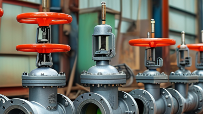
Under IEC 60534, valve selection begins with process behavior, not actuator size. Choose a linear globe valve for accurate throttling, high pressure drops, and stable modulating service. Rotary valves suit larger pipelines, compact layouts, and lower torque demands. Ball and butterfly designs can respond quickly, but their control accuracy varies near closed travel.

IEC 60534-2-1 defines standardized flow-capacity sizing methods, including Cv calculations and correction factors. Use actual pressure, temperature, density, and vapor-pressure data. Do not size from line diameter alone. Oversized valves often hunt around the setpoint and suffer poor resolution. A practical target keeps normal flow near the middle of the travel range. This is not a perfect rule.

A 2024 industrial valve market report from Grand View Research estimated the global market at more than USD 78 billion in 2023, with continued growth through 2030. That growth reflects stricter process control and expanding automation. Yet market growth does not replace field judgment. I have seen first-pass selections fail because air supply pressure was assumed, not measured. Check available instrument air, fail-open or fail-closed action, leakage class, hysteresis, and actuator torque. For rotary valves, confirm torque throughout the full stroke. For linear valves, inspect cavitation risk and characteristic selection. Equal-percentage trim often handles changing loads better, while linear trim may suit steadier systems. Performance reports from control-valve testing also show that installed behavior can differ from catalog data. Pipeline fittings, reducers, and poor positioner tuning matter. Small details matter.

Size Cv and Check Cavitation, Flashing, and 10–30% Rated Travel Margin

Choosing a pneumatic control valve in 2026 starts with process data, not catalogue preference. Calculate required Cv from flow, pressure drop, density, and temperature. Use IEC 60534-2-1 and ISA-75.01.01 equations for liquid or gas service. A valve that is too small may starve the process. An oversized valve often hunts near its seat.

Cavitation requires careful pressure analysis. Compare downstream pressure with liquid vapor pressure at operating temperature. NIST Chemistry WebBook lists water vapor pressure near 2.34 kPa at 20°C and about 47.4 kPa at 80°C. This difference can radically change the risk profile. Cavitation forms when local pressure falls below vapor pressure, then bubbles collapse downstream. Flashing is different. The liquid remains vaporized after the pressure drop. Use IEC 60534-8-4 guidance when evaluating hydrodynamic noise and vibration. My practical mistake was trusting average pressure instead of checking the minimum pressure point.

Tips: Select normal operation around 60–80% rated travel. Keep roughly 10–30% rated capacity or travel margin for fouling, seasonal demand, and uncertain data. Do not hide a poor calculation behind extra margin. Check shutoff pressure, actuator force, air failure position, and installed flow characteristics. Verify the final choice with measured site data. Reports from the U.S. Department of Energy’s Industrial Assessment Centers repeatedly emphasize measurement-based efficiency decisions, yet field measurements are still often incomplete. That weakness deserves attention.

Specify Actuators, Positioners, and SIL Requirements Under IEC 61508

Choosing a pneumatic control valve in 2026 starts with the safety function, not the catalog. Under IEC 61508, define the required safe state: close, open, or hold position. Then document process pressure, temperature, flow range, leakage class, and available air pressure. A valve may meet control duties yet fail during a shutdown demand. That distinction matters.

Select actuator torque with a real margin across breakaway, running, and end-position loads. Spring-return actuators provide a clear fail action, while double-acting designs need a dependable air-failure strategy. Check travel time at minimum supply pressure, not only at nominal conditions. In field reviews, calculations often look adequate until cold air, sticky packing, or high differential pressure appears. Recheck them.

Treat the positioner as part of the safety loop when its diagnostics or feedback support the function. Confirm response time, output pressure, air consumption, diagnostic coverage, and vibration resistance. For SIL claims, review the complete subsystem: valve, actuator, solenoid, position feedback, logic solver, proof-test interval, and repair assumptions. Calculate PFDavg using verified failure data. Do not copy a SIL label from one component. SIL belongs to the safety function, not the product alone. Record bypass controls and test intervals clearly. Small omissions become expensive lessons.

How to Choose a Pneumatic Control Valve in 2026?

IEC 61508 Safety Integrity Level (SIL) selection based on the maximum permitted average probability of dangerous failure on demand (PFDavg).

How to use this chart: For low-demand safety functions, IEC 61508 defines SIL targets by PFDavg ranges: SIL 1 is ≥10⁻² to <10⁻¹, SIL 2 is ≥10⁻³ to <10⁻², SIL 3 is ≥10⁻⁴ to <10⁻³, and SIL 4 is ≥10⁻⁵ to <10⁻⁴. Select the pneumatic actuator, safety positioner, solenoid valve, valve body, diagnostics, proof-test interval, and redundancy architecture as a complete safety loop. The final SIL capability must be verified through a documented IEC 61508 calculation rather than inferred from the valve alone.

Verify Air Quality to ISO 8573-1 and Confirm 2026 Maintenance Data

How to Choose a Pneumatic Control Valve in 2026?

Air quality should be checked before comparing valve materials, flow ratings, or actuator sizes. Specify compressed air according to ISO 8573-1, including particles, water, and total oil. The required class depends on the process and installation environment. Clean air is not automatically dry air. Test it at the valve inlet, not only near the compressor. A portable analyzer, drain inspection, and filter differential-pressure reading can reveal problems hidden by clean-looking tubing.

Ask for current maintenance data before approving the valve. Review cycle counts, response-time changes, leakage records, supply-pressure drops, and actuator failures from the last twelve months. In 2026, a useful maintenance file should connect each event with operating conditions. Temperature, humidity, load changes, and emergency stops matter. They can explain why an apparently suitable valve wears early. Data logging is helpful, but poor sensor calibration can create false confidence.

During site reviews, technicians often find water collecting below the filter bowl. That detail matters. I once treated intermittent sluggish movement as a valve-sizing issue; the real cause was wet air after a failed dryer drain. The first conclusion was wrong. Select a valve with the correct fail position, control range, connection standard, and service access. Leave room for inspection. A compact installation may save space today but increase maintenance time later. Check the records twice. Errors remain possible.

How to Choose a Pneumatic Control Valve in 2026? - Verify Air Quality to ISO 8573-1 and Confirm 2026 Maintenance Data

Evaluation Area 2026 Verification Item Reference or Target Value Selection or Maintenance Action
Compressed-Air Purity Verification
Particles Measure particle concentration downstream of the final filter. Use the selected ISO 8573-1 particle class; results are expressed as particles per cubic metre at 1 bar absolute. Select a valve with cleanable internal passages and install filtration suitable for the required particle class.
Pressure dew point Confirm the lowest ambient temperature around the air lines and valve actuator. The pressure dew point should remain below the coldest operating temperature to prevent condensation and freezing. Use a refrigerated or desiccant dryer when the required dew point is lower than the compressor-room conditions.
Oil content Check total oil concentration, including liquid, aerosol, and vapor where applicable. Specify the ISO 8573-1 oil class according to actuator, seal, instrument, and process requirements. Avoid uncontrolled oil carryover; verify that lubricated and non-lubricated components are compatible.
Recommended starting point Compare the measured result with the valve supplier’s air-quality requirement. A commonly used general-purpose reference is ISO 8573-1 Class 3:4:3, subject to the actual actuator and process specification. Use a cleaner class when low-temperature operation, sensitive positioners, food contact, or critical control performance is involved.
ISO 8573-1 Reference Limits
Particle Class 1 Maximum concentration: ≤20,000 particles/m³ from 0.1–0.5 μm; ≤400 particles/m³ from 0.5–1 μm; ≤10 particles/m³ from 1–5 μm. Use only where very high particle cleanliness is specifically required.
Particle Class 2 Maximum concentration: ≤400,000 particles/m³ from 0.1–0.5 μm; ≤6,000 particles/m³ from 0.5–1 μm; ≤100 particles/m³ from 1–5 μm. Consider for sensitive instrumentation and demanding control systems.
Particle Class 3 No limit specified for 0.1–0.5 μm; ≤90,000 particles/m³ from 0.5–1 μm; ≤1,000 particles/m³ from 1–5 μm. Often suitable as a practical particle target for general pneumatic control applications.
Water Classes 1–6 Maximum pressure dew point: Class 1 ≤−70°C; Class 2 ≤−40°C; Class 3 ≤−20°C; Class 4 ≤+3°C; Class 5 ≤+7°C; Class 6 ≤+10°C. Choose the water class after considering ambient temperature, line routing, and freeze risk.
Oil Classes 1–6 Maximum total oil concentration: Class 1 ≤0.01 mg/m³; Class 2 ≤0.1 mg/m³; Class 3 ≤1 mg/m³; Class 4 ≤5 mg/m³; Class 5 ≤25 mg/m³; Class 6 has no specified limit. Use measured oil data rather than compressor type alone when defining the valve air-quality requirement.
Pneumatic Control Valve Selection Data
Operating pressure Record minimum, normal, and maximum supply pressure at the actuator inlet. The valve actuator and accessories must be rated above the maximum available pressure and must operate at the minimum pressure. Check fail-safe position, spring range, tubing size, and regulator capacity.
Flow capacity Compare required flow coefficient or effective flow area with the process demand. The selected capacity should achieve the required stroke speed without excessive pressure drop or unstable control. Avoid oversizing, which can reduce controllability at low flow, and avoid undersizing, which can slow response.
Temperature and materials Confirm media temperature, ambient temperature, humidity, and chemical exposure. Elastomers, body materials, seals, and lubricants must be compatible with the operating environment. Specify corrosion-resistant materials or protective enclosures for outdoor, coastal, or chemically aggressive areas.
2026 Baseline Maintenance and Verification Schedule
Every operating shift or daily Inspect leaks, abnormal noise, position indication, supply pressure, and visible condensate. No significant leakage, pressure fluctuation, or unexpected valve movement. Log abnormalities and correct leaks promptly; do not rely on audible inspection alone in noisy areas.
Monthly Drain filters and separators, inspect tubing and fittings, and check regulator pressure. Drain frequency should be increased when condensate accumulation is visible before the planned interval. Replace damaged tubing, blocked silencers, or saturated filter elements.
Quarterly Test full stroke, fail position, response time, and positioner or solenoid operation. Compare response and travel data with the commissioning baseline. Investigate sluggish movement, hunting, incomplete travel, or repeatability changes.
Every six months Review air-quality test results and inspect actuator seals, mounting hardware, and corrosion protection. Verify continued compliance with the specified ISO 8573-1 class. Shorten the interval when water, oil, dust, or outdoor exposure is higher than expected.
Annually in 2026 Perform documented functional testing, calibration verification, leak assessment, and safety review. Retain test date, instrument identification, measured values, acceptance limits, and corrective actions. Update the maintenance record and revise the interval using actual failure, contamination, and performance data from 2026.
After two years or condition-based Assess whether seals, diaphragms, springs, tubing, filters, or actuator components require replacement. Use condition, cycle count, leakage, response time, and inspection results rather than calendar age alone. Complete an overhaul only when justified by the service environment, manufacturer instructions, or measured deterioration.

Note: ISO 8573-1 classes describe compressed-air purity. Final valve selection and maintenance intervals must be confirmed against the actual process conditions, safety requirements, equipment instructions, and measured site data.