Choosing the right motorized valve in 2026 requires more than matching pipe size and voltage. The correct choice must fit the fluid, pressure, temperature, flow pattern, and control system. A valve that works well in clean water may fail quickly in abrasive slurry. Small details matter.
Dr. Bela G. Lipták, a respected process-control engineer, stated, “The control valve is the most important final control element.” His observation remains relevant for modern motorized valve selection. The actuator, valve body, seals, feedback signal, and emergency position must work as one system. Otherwise, automation can hide a mechanical weakness until production stops.
Begin with the process conditions. Record minimum and maximum pressure, operating temperature, media chemistry, and required flow rate. Then compare quarter-turn and linear designs. Consider torque margins carefully. A tight valve may need far more starting torque than expected. Check power-loss behavior, enclosure protection, manual override, cycle frequency, and communication protocols. Compatibility is not guaranteed.
No selection table is perfect. Real installations include vibration, condensation, wiring errors, and changing demand. A technically elegant choice can still disappoint in the field. Review maintenance access and replacement availability before approval. Ask for tested performance data, not attractive promises. The best motorized valve is not always the most advanced model. It is the one that operates reliably, safely, and predictably within the actual process. That judgment takes evidence. And sometimes, humility.
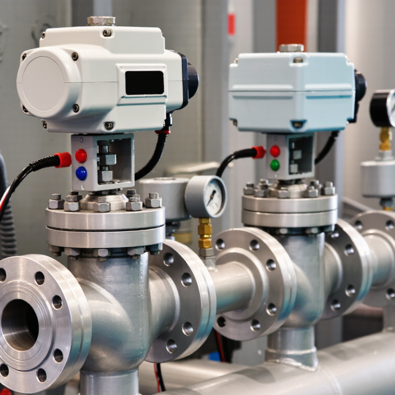
How to Choose the Right Motorized Valve in 2026?
A motorized valve combines a valve body with an electric actuator. The actuator opens, closes, or positions the valve automatically. This setup improves control in systems that need repeatable flow regulation. Start with the medium, pipe size, pressure, and temperature. Water, steam, air, and chemical fluids require different valve materials and sealing methods. A valve that works well for clean water may fail quickly with abrasive particles.
Common application types include heating systems, cooling loops, irrigation networks, water treatment, and industrial process lines. Ball valves suit fast shutoff and compact installations. Butterfly valves work well on larger pipes with moderate pressure. Globe valves offer more precise throttling, although they may create higher flow resistance. Check the actuator’s torque, voltage, response time, and manual override. Outdoor installations also need suitable protection against moisture and dust. Small details matter.
Tips: Match the actuator to the valve’s real operating load, not only its catalog rating. Leave extra torque capacity for aging seals and pressure changes. Test the full travel before commissioning, then inspect wiring and fail-safe behavior. A common mistake is selecting by pipe diameter alone. I still revisit that assumption during system reviews, because fluid conditions often change after installation. When uncertain, consult current technical data and a qualified engineer. Test under realistic conditions.
| Valve Type | Operating Movement | Typical Size Range | Flow-Control Capability | Common Applications | Main Advantages | Important Selection Considerations |
|---|---|---|---|---|---|---|
| Motorized Ball Valve | Quarter-turn, usually 90° | Approximately DN15–DN300 | Excellent shutoff; suitable for on/off and limited modulating service when fitted with a proportional actuator | Water distribution, HVAC, compressed air, fuel, process liquids, irrigation | Low pressure loss, compact construction, fast operation, reliable tight shutoff | Check media compatibility, actuator torque, seal material, temperature, and whether the valve is rated for continuous throttling |
| Motorized Butterfly Valve | Quarter-turn, usually 90° | Approximately DN50–DN2000 or larger | Good for isolation and moderate flow regulation with a suitable actuator and control signal | Cooling water, chilled-water systems, ventilation, fire-water systems, wastewater, large pipelines | Lightweight, economical at large diameters, compact face-to-face dimension, low operating torque at stable conditions | Evaluate disc pressure drop, seat material, flow velocity, cavitation risk, and required shutoff class |
| Motorized Globe Valve | Linear stem movement | Approximately DN15–DN300 | Very good and precise throttling control | Steam, hot water, process control, heat exchangers, pressure and temperature regulation | Stable control characteristics, good rangeability, suitable for frequent modulation | Expect higher pressure loss than a ball or gate valve; size the trim for flow coefficient, noise, flashing, and cavitation |
| Motorized Gate Valve | Multi-turn linear stem movement | Approximately DN50–DN1200 or larger | Primarily for fully open or fully closed service; not recommended for regular throttling | Water mains, oil and gas pipelines, power plants, raw-water systems, isolation duties | Very low pressure loss when fully open and suitable for large-diameter isolation | Requires adequate installation space and longer travel time; avoid partially open operation that may cause vibration and seat damage |
| Motorized Diaphragm Valve | Linear stem movement with flexible diaphragm | Approximately DN15–DN300 | Good isolation and moderate control; highly dependent on diaphragm design | Corrosive chemicals, wastewater, slurry, hygienic processes, contaminated or particulate-containing fluids | Fluid is isolated from the stem and actuator; suitable for corrosive, abrasive, or dirty media | Confirm diaphragm compatibility, pressure-temperature limits, permeation resistance, and maintenance access |
| Motorized Plug Valve | Quarter-turn, usually 90° | Approximately DN50–DN900 | Mainly on/off; specialized designs can provide throttling | Slurry, wastewater, dry bulk handling, gas service, industrial process isolation | Full-port options handle dirty media and can provide dependable isolation | Consider operating torque, plug lubrication, solids concentration, sealing method, and actuator sizing |
| Motorized Check Valve | Automatic flow-dependent movement; some designs include powered override | Approximately DN25–DN1200 | Not normally used for continuous flow regulation | Pump discharge, water systems, process lines, backflow prevention, emergency isolation | Prevents reverse flow and can support controlled closing in selected systems | Check closing speed, water-hammer risk, minimum flow, pressure drop, and the need for an external actuator |
| Selection Dimension | What to Check | Why It Matters | Typical Decision Guidance |
|---|---|---|---|
| Fluid and Compatibility | Liquid, gas, steam, slurry, corrosive chemicals, solids, viscosity, and cleanliness | The body, trim, seat, seal, and diaphragm must withstand the process medium | Use corrosion-resistant materials and resilient seals only after verifying chemical and temperature compatibility |
| Pressure and Temperature | Maximum and minimum operating pressure, differential pressure, temperature, and pressure class | Ratings often change with temperature and material selection | Select from the valve pressure-temperature chart, not from nominal size alone |
| Flow and Valve Sizing | Normal, minimum, and maximum flow; allowable pressure drop; flow coefficient; line velocity | Incorrect sizing may cause poor control, noise, cavitation, erosion, or excessive energy loss | Size for the required operating range rather than simply matching the pipe diameter |
| Control Function | On/off, modulating, emergency shutdown, isolation, pressure control, or flow control | Valve type and actuator requirements differ substantially by duty | Use ball, butterfly, gate, or plug valves mainly for isolation; consider globe or control-oriented designs for precise modulation |
| Actuator and Power | Voltage, current, torque or thrust, operating time, duty cycle, fail position, and manual override | The actuator must move the valve under worst-case differential pressure and environmental conditions | Choose fail-open, fail-closed, or fail-in-place behavior according to process safety requirements |
| Signal and Integration | On/off signal, analog modulation, position feedback, communication protocol, and local control | Compatibility with the building-management system, PLC, SCADA, or process-control system is essential | Confirm input and output signals, feedback accuracy, wiring, and commissioning requirements |
| Environment and Maintenance | Indoor or outdoor location, humidity, dust, chemicals, vibration, washdown, ambient temperature, and access | Environmental exposure affects actuator reliability, enclosure selection, and service life | Check enclosure protection, corrosion resistance, inspection access, replacement parts, and preventive-maintenance needs |
Note: Size ranges, pressure limits, temperature limits, flow coefficients, and actuator requirements are typical industry values and vary by valve design, material, standards, and service conditions. Final selection should be confirmed using the applicable manufacturer data sheet and project specifications.





©Copyright 2020 Gosco Valves. All rights reserved.