Please upgrade your web browser now. Internet Explorer 6 is no longer supported.>

How to Wire a 7 Pin Trailer Socket Correctly?

Wiring a 7 Pin Trailer Socket correctly is more than matching seven colored wires. It is a safety-critical connection between your tow vehicle and trailer. Each terminal must carry the correct function, including tail lamps, brake lamps, indicators, reverse power, ground, and auxiliary supply. A single loose earth wire can make several lights fail together. That small fault may appear only when rain reaches the connector.

Mark Polk, a respected RV electrical educator, offers a practical reminder: “Test every circuit before you tow.” His advice reflects real workshop experience. A wiring diagram gives direction, but careful testing confirms the finished connection. Wire colors can differ between vehicles, sockets, and aftermarket harnesses. Never trust color alone. Confirm each circuit with a multimeter, a test lamp, or a dedicated trailer tester.

This guide explains how to identify the socket terminals, prepare the cable, and secure every connection. You will see why the ground wire deserves extra attention. You will also learn how to inspect pins for corrosion, loose screws, and damaged insulation. Keep the process simple. Work slowly.

There is room for human error. I have seen correctly arranged wires fail because one terminal screw was barely tight. Another common mistake is confusing the viewing direction of the socket. The diagram may show the front, while you are holding the rear. That detail matters.

Before connecting power, isolate the vehicle battery where appropriate and compare the pin layout with your equipment manual. A final lighting test should cover every function, including the brakes, indicators, and reverse lamps. Careful wiring is not glamorous, but it prevents dark surprises on the road.
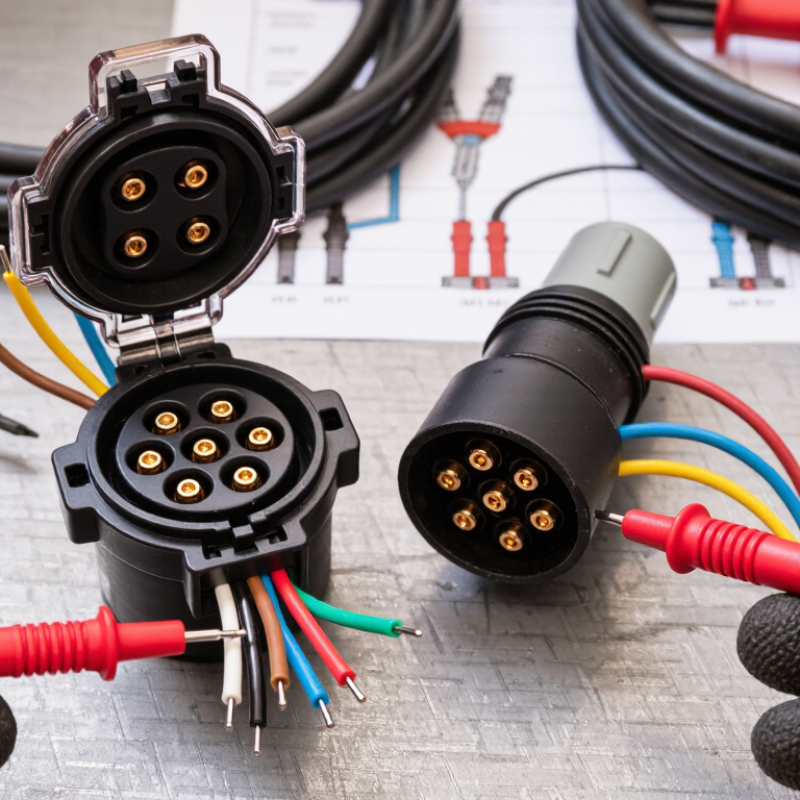
How to Wire a 7 Pin Trailer Socket Correctly?

Identify the 7-Pin Trailer Socket Layout and Wiring Functions

How to Wire a 7 Pin Trailer Socket Correctly?

The seven-pin layout depends on the socket standard, so identify it before touching any wire. A common ISO 1724 arrangement uses pin 1 for the left turn signal, pin 2 for the rear fog lamp, and pin 3 for earth. Pin 4 operates the right turn signal. Pins 5 and 7 control the right and left tail lamps, while pin 6 supplies the brake lamps. View the socket from its mating face, because the pin direction may appear reversed from the rear.

Australian seven-pin flat sockets often use a different function map. Pin 1 usually serves the left indicator, pin 2 the reverse lamp, and pin 3 the earth return. Pin 4 operates the right indicator, pin 5 the electric brake circuit, pin 6 the stop lamps, and pin 7 the tail lamps. Wire colors can help, but they are not universal. Never trust color alone.

Use a wiring chart and a multimeter before crimping terminals. Check each pin with the vehicle lights switched on, then confirm the earth connection under load. Keep the test probe dry. My early wiring mistake was assuming two sockets shared the same layout; they did not. A loose earth can create dim lamps, strange signal behavior, or intermittent braking. Secure the cable away from sharp edges, leave a small service loop, and inspect every terminal after fitting. Do not force a connector that feels wrong.

Gather the Required Tools, Materials, and Safety Equipment

Before wiring a 7-pin trailer socket, gather every tool and safety item within reach. Use the vehicle and trailer wiring diagrams, not memory. Pin functions and wire colours can vary between vehicles. Keep a digital multimeter nearby for checking voltage, continuity, and grounding. A small inspection light also helps reveal damaged insulation or hidden corrosion.

Your tool kit should include insulated screwdrivers, wire strippers, a crimping tool, side cutters, and a torque screwdriver. Prepare suitable terminals, heat-shrink tubing, cable ties, protective conduit, and spare fuses. Use waterproof connectors where moisture may enter. Wear safety glasses and insulated gloves. Park on level ground, engage the parking brake, and disconnect the battery before handling wiring. Never test a live circuit with damaged leads.

Before cutting anything, photograph the existing connections and label each wire. Clean the socket area and remove rust from the grounding point. After connecting each circuit, gently pull the wire to check its grip. Test the tail lights, brake lights, indicators, reverse circuit, and ground separately with a multimeter and trailer connected. A helper can confirm the lights from behind. If a reading seems strange, stop and inspect it. Do not assume the socket is faulty. I have seen tidy wiring fail because the ground connection was overlooked. A neat job can still be wrong. Take a little longer.

How to Wire a 7 Pin Trailer Socket Correctly: Required Tools, Materials, and Safety Equipment
Category Item Recommended Quantity Typical Specification Purpose or Use Safety or Quality Check
Tool Digital multimeter 1 DC voltage, continuity, and resistance functions Identify circuits, confirm polarity, and test the completed socket connections. Verify the meter is set correctly before testing a live circuit.
Tool Wire stripper and cutter 1 Suitable for common automotive wire sizes Remove insulation cleanly and cut conductors to the required length. Avoid nicking copper strands, which can weaken the connection.
Tool Insulated crimping tool 1 Compatible with insulated automotive terminals Secure terminals to the trailer wires with a firm mechanical crimp. Pull-test each crimp gently before installing it in the socket.
Tool Screwdriver set 1 set Flat-head and cross-head drivers Remove the socket cover and tighten terminal screws or mounting fasteners. Use the correct tip size to prevent damaged screw heads.
Material 7-pin trailer socket 1 12-volt socket with numbered terminals Provide the connection point between the towing vehicle and trailer lighting circuits. Confirm the terminal numbering and wiring layout before connecting wires.
Material Automotive multi-core cable As required Seven conductors; commonly 1.0–2.5 mm² per conductor Carry earth, tail-lamp, indicator, stop-lamp, and auxiliary circuit signals. Use cable with insulation rated for vehicle vibration, moisture, and temperature.
Material Insulated crimp terminals 8–12 Correct size for the cable cross-section Terminate wires at the socket or join replacement sections of cable. The terminal barrel must fully grip the conductor without exposed loose strands.
Material Heat-shrink tubing 1 length Heat-shrink ratio around 2:1; sized for the cable and terminal Seal repaired or joined conductors against moisture and reduce strain on the joint. Apply controlled heat and keep the heat source moving to avoid melting insulation.
Material Cable ties and protective conduit As required Weather-resistant ties; flexible split conduit where abrasion is possible Route and secure the harness away from exhaust components, sharp edges, and moving parts. Leave enough slack for articulation near the hitch without allowing cable drag.
Safety Equipment Safety glasses 1 pair Impact-resistant eye protection Protect the eyes while cutting, stripping, drilling, or working beneath the vehicle. Wear throughout the installation and testing process.
Safety Equipment Insulated work gloves 1 pair Close-fitting, cut-resistant workshop gloves Protect hands from sharp brackets, wire strands, and edges around the vehicle. Gloves do not replace electrical isolation; disconnect the battery first.
Safety Equipment Wheel chocks and parking brake 2 chocks Suitable for the vehicle wheel size Prevent unintended vehicle movement during installation and circuit testing. Park on a stable, level surface and engage the parking brake.
Safety Equipment Vehicle service manual or wiring diagram 1 Diagram matching the vehicle and trailer socket configuration Confirm circuit functions, wire identification, fuse locations, and grounding points. Do not rely on wire color alone; verify every circuit with a meter.

Prepare the Trailer Wires and Socket Terminals for Installation

Before wiring a 7-pin trailer socket, disconnect the towing vehicle’s battery and inspect the cable harness. Dirt, cracked insulation, or green corrosion can cause unreliable signals. I have found that a clean workbench prevents more mistakes than rushing beside the trailer. Lay out the wires, socket, seals, terminals, heat-shrink tubing, a wire stripper, and a calibrated crimping tool.

Check the socket’s wiring diagram before identifying each terminal. Pin layouts can differ between regional standards, so never trust wire colors alone. Label every conductor with tape, then cut back damaged sections until the copper looks bright. Strip only the required length. Too much exposed copper may touch another terminal. Too little copper may produce a weak crimp. Twist loose strands carefully, but do not solder a flexible wire before crimping unless the terminal instructions allow it.

Insert each prepared wire fully into its terminal, then crimp with steady pressure. A proper crimp should hold firmly when pulled by hand. Seal the connection with heat-shrink tubing, keeping moisture away from the copper. Secure the harness with a strain-relief clamp, leaving a gentle service loop near the socket. I once assumed a tight bend looked tidy; it later stressed the terminals. That was avoidable. Test continuity and each lighting function with a multimeter before reconnecting the battery. Recheck the ground connection, because many mysterious faults begin there.

Connect Each Wire to the Correct 7-Pin Socket Terminal

How to Wire a 7 Pin Trailer Socket Correctly?

A 7-pin trailer socket works only when each wire reaches its correct terminal. In the common European 12N layout, terminal 1 carries the left indicator, using yellow wire. Terminal 2 powers the rear fog lamp, usually with blue wire. Terminal 3 is the earth return, normally white. Keep this connection clean and firmly tightened.

Terminal 4 connects to the right indicator through the green wire.

Terminal 5 supplies the right tail lamp with brown wire.

Terminal 6 operates the brake lamps and commonly uses red wire.

Terminal 7 supplies the left tail lamp, often through black wire.

Wire colours can differ. Check the socket diagram, not just the insulation.

Turn off the vehicle before opening the socket. Strip only enough insulation to fit each clamp. A loose strand can touch another terminal.

I once trusted matching colours and found the trailer lights reversed, so testing matters.

Use a multimeter or a suitable 12-volt tester, then check indicators, tail lamps, brake lamps, fog lamp, and earth continuity. Look for green corrosion around the contacts. A small amount can create intermittent faults.

Keep the cable supported near the socket, and allow a gentle loop for movement. Do not force the cover closed; trapped wires often fail later.

Test the Trailer Lights and Troubleshoot Wiring Problems

How to Wire a 7 Pin Trailer Socket Correctly?

Testing every trailer light is more reliable than trusting the socket diagram alone. Pin layouts can vary, so check the vehicle and trailer wiring charts first. With the trailer connected, switch on the running lights, left indicator, right indicator, and brake lights. Test the reverse light and auxiliary circuit if fitted. A digital multimeter can confirm voltage at each pin. The reading should remain steady while the light operates. Do not rely only on brightness.

If one light fails, inspect the ground connection before replacing the lamp. A weak ground can cause dim lights, flickering indicators, or several lamps glowing together. Clean the frame contact and check for loose terminals, damaged insulation, or moisture inside the socket. I once blamed a faulty bulb, but the real problem was a poorly crimped ground wire. That mistake was avoidable. If no voltage reaches a pin, test the fuse, socket, and tow vehicle wiring in that order.

Tips: Use a trailer-light tester when available, or ask another person to watch the lamps. Move the cable gently during testing. If the light flickers, the connector or wire may be damaged. Record each test result instead of relying on memory. Recheck the pin order before reconnecting anything, because one misplaced wire can create several confusing faults.