Please upgrade your web browser now. Internet Explorer 6 is no longer supported.>

How to Install Double Head Bolts?

Double Head Bolts connect components where a threaded fastener is needed at both ends. You may see them in machinery, flanged joints, engine assemblies, and other equipment. Their installation can look simple. Small errors, however, may cause poor alignment, damaged threads, or an unreliable joint.

This guide explains how to install Double Head Bolts with care. It covers checking bolt size, thread pitch, material, and length against the equipment manufacturer’s specifications. Before installation, inspect the threads and clean the receiving hole. Start the bolt by hand to help prevent cross-threading. A bolt that binds early needs attention, not extra force.

Fit matters. The bolt should engage correctly without bottoming out in a blind hole. Use an approved installation method and avoid gripping or damaging the exposed threads. Tighten the assembled joint to the specified torque, using the stated lubrication condition; lubricant can change clamping force. No universal torque value fits every bolt and application. Keep the work area stable, and follow the equipment’s service instructions. When specifications are missing or parts do not match, pause and verify them with a qualified technician or the manufacturer. I’ve seen this step treated as optional. It isn’t. Proper installation takes patience, and even a careful process deserves a final inspection.
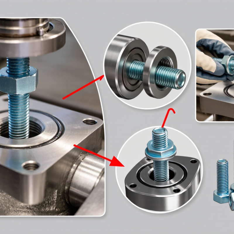
How to Install Double Head Bolts?

Identify the Double-Head Bolt Type and Its Application

A double-head bolt is usually a stud with threads at both ends, but its end geometry matters. A tap-end stud has a shorter end for engagement in a tapped hole and a longer end for a nut. A double-ended stud used with two nuts may have different thread lengths or a plain center section.

Check diameter, pitch, overall length, end lengths, and head or grade markings. Small details matter.

Match the type to the joint. Tapped-end studs suit machinery housings and engine components; studs with nuts at both ends commonly secure pipe flanges. For flanges, ASME B16.5 provides dimensional and pressure-temperature ratings that help establish fit, but it does not replace the project’s material specification.

ASTM A193/A193M lists Grade B7’s minimum tensile strength as 125 ksi and yield strength as 105 ksi for diameters up to 2.5 inches.

These values do not make B7 suitable for every service. Confirm temperature, corrosion exposure, mating materials, and the specified grade before installation.

A frequent inspection miss is treating similar-looking studs as interchangeable. Check the documentation, too.

Gather the Required Tools and Prepare the Mounting Surface

Before installing double head bolts, identify the thread size, pitch, and required engagement depth from the equipment instructions. A thread-pitch gauge and caliper help confirm measurements; do not rely on appearance alone. Gather the specified drill bits, tap, wrench, torque wrench, and safety glasses. Use a torque wrench only when a tightening value is provided.

Clean the mounting surface with a lint-free cloth and a suitable cleaner. Remove oil, loose paint, burrs, and old sealant without grinding away sound material. Check that the face is flat and that each hole aligns with the mating part. A small flashlight helps reveal damaged threads. Keep debris out of open holes. If a hole needs drilling or tapping, use the specified size and keep the tool square to the surface; forcing it can create crooked threads.

I have learned that “close enough” alignment often becomes a frustrating assembly problem. It is tempting to start a bolt with a wrench, but turn it gently by hand first. It should engage smoothly. Stop if it binds, and inspect the threads rather than applying more force. A little patience here saves rework.

How to Install Double Head Bolts? - Gather the Required Tools and Prepare the Mounting Surface
Stage Tool or Check Purpose Practical Guidance
Gather tools Thread-pitch gauge and caliper Identify the stud’s thread pitch and measure its diameter and length. Confirm the measurements against the equipment drawing or service instructions before installation.
Gather tools Correctly sized thread chaser or tap Clean or restore the receiving thread in the mounting hole. Use the matching thread specification. A cutting tap removes material, so use it only when appropriate for the hole and repair procedure.
Gather tools Non-metallic brush, lint-free cloth, and approved cleaner Remove loose debris, oil, and residue from the hole and surrounding surface. Follow the cleaner’s instructions and allow the area to dry. Keep debris out of blind holes.
Gather tools Inspection light and straightedge Check the hole, threads, and mounting face for damage or unevenness. Do not install a stud into cracked, stripped, or visibly damaged threads without an approved repair.
Prepare surface Clean mounting face Provide a flat, debris-free contact surface for the attached component. Remove old gasket material or burrs without gouging the face. Keep the hole opening clear.
Prepare hole Thread and depth check Verify that the internal threads are clean and the hole has adequate depth. For a blind hole, confirm the stud will not bottom out before reaching the specified engagement depth.
Before installation Specification check Confirm stud orientation, thread engagement, lubricant or locking compound, and installation method. These requirements vary by application. Use the equipment or engineering specification rather than assuming a universal value.

Align the Bolt and Thread It into the Base

Before installing a double head bolt, check the drawing to identify which end enters the base. The two ends may have different thread lengths. Confirm that the bolt pitch matches the tapped hole, then inspect both threads for damage. Clean the hole with a suitable brush and remove loose debris. Keep dirt out of the base.

Set the bolt directly over the hole and keep its axis square to the surface. Start the threads by hand, turning gently until the bolt advances several turns without resistance. Keep it square. If it binds early, stop and back it out; forcing it can cross-thread the hole. A slight wobble can be easy to miss, so check alignment from two directions. It is worth pausing here.

Once the bolt turns freely, install it with a suitable stud driver or another approved method. Avoid gripping the exposed threads with pliers. Do not assume the bolt should be tightened until it bottoms out; use the specified engagement depth and installation torque. Apply lubricant only if the equipment instructions call for it, since lubrication can change clamping force. If the bolt rocks, feels rough, or will not reach the specified depth, inspect the hole and threads before continuing.

Tighten the Bolt to the Specified Torque

How to Install Double Head Bolts?

Tighten the Bolt to the Specified Torque

Start with clean, undamaged threads and confirm the required torque in the equipment’s service instructions. Torque values can change with thread condition, lubrication, and fastener design, so avoid relying on a general chart. Thread the bolt into the component by hand to check alignment. It should turn smoothly, without binding. If the instructions specify an installation torque for the bolt itself, use that value and the recommended installation tool. Do not assume it matches the torque for the nut.

Fit the washer and nut as specified, then tighten the nut to the stated torque. If the bolt begins turning with the nut, stop and use a suitable stud-holding method rather than gripping the threads with pliers. Check that the washer sits flat and the joint faces are fully seated. After tightening, inspect the exposed thread length and look for gaps or signs of misalignment. Even careful work can miss a detail, so recheck the torque procedure before putting the assembly into service.

Inspect Thread Engagement and Confirm the Installation

After installing a double head bolt, inspect how its threaded end engages the tapped hole. Clean both sets of threads and remove oil, grit, or damaged fragments before checking. Start the bolt by hand. It should turn smoothly without rocking or binding. Resistance near the start can signal crossed threads, not a need for extra force.

Check the specified thread engagement and exposed length against the equipment drawing or service instructions; there is no universal depth for every assembly. A flashlight can help reveal whether the bolt is seated evenly, while a straightedge can show whether neighboring bolts protrude consistently. Do not force the bolt against the bottom of a blind hole. I have learned that “it feels tight” is not a reliable measurement. That matters.

Confirm that the seating end is secure and that the exposed threads are clean, undamaged, and long enough for the nut and any required washer. Hand-start the nut through several turns before using a wrench. If it catches, back it off and inspect the threads again. Tighten the assembly using the specified sequence and torque value, with the stated lubrication condition; lubricant can change clamping force. Recheck alignment and seating before returning the equipment to service. If engagement remains uncertain, pause and consult the component documentation rather than guessing.

Double-Head Bolt Installation: Check Thread Engagement

The chart shows a common rule-of-thumb of one nominal diameter (1D) of thread engagement in steel. For example, an M10 stud has a 10 mm 1D reference. This is a screening guideline, not a universal acceptance criterion; confirm the required engagement against the engineering specification, mating material, and loading. After installation, verify engagement and check that the stud is seated and aligned as specified.