Please upgrade your web browser now. Internet Explorer 6 is no longer supported.>

7 Tips for Choosing a Temperature Control Valve

A temperature control valve can look simple on a piping diagram. In service, it must respond to changing loads, fluid conditions, and control signals without creating instability. A poor match may cause temperature swings, excessive cycling, or unnecessary wear. Small details matter. A narrow pipe run, a sticky actuator, or a fluctuating supply pressure can change how the valve behaves.

Béla Lipták, a process-control author and editor, has written extensively about matching control equipment to process requirements. A practical paraphrase of that guidance is: “Choose the valve for the process, not just the catalog.” That distinction shapes these seven tips: define the medium and operating temperature range; estimate flow capacity; check pressure drop; select compatible body and trim materials; consider response speed; match the actuator and control signal; and plan for inspection and maintenance. Each choice depends on actual operating conditions, not a single headline specification. There is no perfect valve. There is a suitable one. Some specifications may still leave uncertainty, so verify assumptions against process data and, when needed, consult a qualified valve specialist. These practical checks can help engineers and buyers compare options with greater confidence and avoid preventable performance problems.
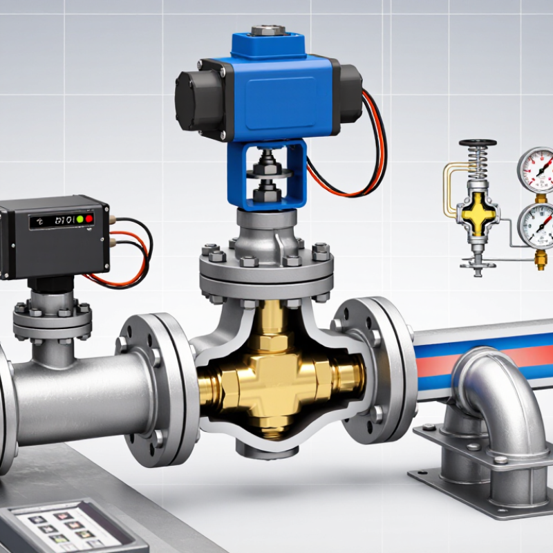
7 Tips for Choosing a Temperature Control Valve

Define the Temperature Control Valve’s Operating Requirements

A temperature control valve should be selected around the job it must perform, not just the pipe size. Define the normal, minimum, and maximum process temperatures. Note the fluid, operating pressure, flow range, and whether the system heats or cools. A water line cycling between 40°C and 70°C presents different demands from a hot-oil loop. Small details matter. Also identify how quickly the temperature can change and whether the valve must respond steadily or rapidly.

Tip: Record the actual operating range, not only the design target. Include startup, shutdown, and seasonal conditions where relevant. Estimate the required flow at both low and peak demand; a valve sized only for peak flow may struggle to control small loads. Check the available pressure difference across the valve, too. It can change as other equipment operates. These figures may be imperfect at first, but clearly marking estimates helps prevent them from being mistaken for measured data.

Consider the control signal and installation conditions before choosing a valve. Confirm the actuator’s power supply, signal type, and fail position. Ask what should happen if power or instrument air is lost. Check fluid compatibility, ambient temperature, vibration, and available maintenance access. A valve tucked behind hot, insulated pipework may be difficult to inspect. One requirement is easy to overlook: whether the process can tolerate brief temperature swings. That answer can change the needed response speed and control range.
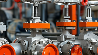

Compare Valve Types and Control Mechanisms

A temperature control valve is not simply “open or closed.” A two-way valve throttles flow as demand changes, while a three-way valve diverts or mixes fluid. Mixing valves can maintain a steadier outlet temperature, but they may keep a pump circulating continuously. Check the piping layout before choosing; a suitable valve can still perform poorly in the wrong circuit.

Actuation matters just as much. Self-acting valves use a sensing element and need no external power, making them useful for simple, local control. Electric actuators support precise positioning and building-control integration; pneumatic actuators suit systems already equipped with instrument air. The IEA’s Energy Efficiency 2023 report estimates that buildings account for about 30% of global final energy use, so stable heating and cooling control has practical energy stakes. That figure is broad, not a promised valve-level saving. Ask for the valve’s flow characteristic, rangeability, and response data, then compare them with actual load variation. A perfectly sized valve on paper may still hunt in a real system. Test it under changing loads, and document what the temperature sensor actually reads.

Match Valve Capacity to Flow and Temperature Conditions

Tip: Match valve capacity to the actual flow range, not just the pipe size. Gather the minimum, normal, and peak flow rates, along with inlet and outlet temperatures. A valve that is too small may struggle to meet demand. An oversized valve can make temperature control unstable, especially at low flow. Pipe diameter alone is not enough.

Tip: Check the operating conditions behind the numbers. Water and steam behave differently, so the same capacity rating does not suit both. Note the fluid, pressure drop across the valve, and expected temperature changes. For example, a heating coil may need full flow during startup but much less once the room warms. Size for both conditions.

Tip: Review the proposed capacity against real operating data where possible. Ask the supplier or a qualified engineer to confirm the sizing assumptions, including pressure and flow units. A calculation is only as sound as its inputs. They may be estimates. If flow varies widely, check that the valve can control steadily across the full range, rather than only at peak demand. That detail is easy to miss.

7 Tips for Choosing a Temperature Control Valve — Match Valve Capacity to Flow and Temperature Conditions
Tip What to Check Practical Example Selection Guidance
1. Define the full operating flow range Record minimum, normal, and maximum flow—not just the design or average flow. Include expected startup and turndown conditions. A heating-water loop may operate from 5 to 30 gpm, with 20 gpm as its normal flow. Check that the valve can control the minimum flow while still passing the maximum required flow. Avoid sizing only for the peak condition.
2. Calculate required valve capacity For water, a common sizing relationship is Cv = Q × √(SG ÷ ΔP), where Q is in US gpm, SG is specific gravity, and ΔP is pressure drop in psi. For 30 gpm of water with a 5 psi pressure drop: Cv = 30 × √(1 ÷ 5), or approximately 13.4. Use the actual fluid properties and available pressure drop. For gases, steam, or flashing liquids, use the appropriate sizing method rather than the water equation.
3. Verify pressure drop at each flow condition Determine the pressure available across the valve at minimum, normal, and maximum flow, accounting for piping, heat exchangers, and other equipment. If the system provides 5 psi across the valve at design flow, that value should be confirmed from the system pressure balance rather than assumed. Too little pressure drop can limit control authority; excessive pressure drop can cause noise, erosion, or cavitation in suitable liquid-service conditions.
4. Match capacity to the process temperature load Estimate the heat duty and the required fluid flow using the supply and return temperatures. For water, heat transfer is approximately 500 × gpm × ΔT in Btu/h under typical conditions. A 20 gpm water flow with a 20°F temperature change transfers approximately 200,000 Btu/h. Confirm that the valve can deliver the flow needed at the actual design temperature difference; a valve opening position alone does not determine heat output.
5. Check fluid temperature and material limits Review the fluid’s minimum and maximum temperature, pressure, chemistry, and any applicable insulation or ambient conditions. A hot-water application operating near 180°F requires valve body, trim, seals, and actuator components rated for the service conditions. Use material and pressure-temperature ratings suitable for the full operating envelope, including credible excursions—not only the normal setpoint.
6. Choose a suitable control characteristic and range Consider the valve’s inherent flow characteristic and usable rangeability, as well as the system’s changing pressure conditions. An equal-percentage characteristic is often considered for systems where pressure drop across the valve changes as flow changes. Confirm the selected characteristic with the control-system design. A valve that is too large may operate near its seat and make stable low-flow control difficult.
7. Confirm actuator and failure response Check required stroke time, control signal, shutoff requirement, and the desired position if power or control air is lost. A heating coil may require the valve to close on loss of power to limit overheating, while another process may require a different safe position. Specify the actuator and fail action based on the process hazard review and control philosophy. Confirm that the actuator can move the valve under the maximum differential pressure.

Check Materials, Connections, and Installation Needs

A temperature control valve should suit the fluid, not just the temperature range on its data sheet. Check the body and trim materials against the fluid’s chemistry, operating temperature, and pressure. Water containing treatment chemicals, for example, may affect metals or elastomers differently from clean water. Confirm seal compatibility too. A small mismatch can cause swelling, leakage, or premature wear. Small details matter. Review the valve’s pressure and temperature limits, then compare them with actual operating conditions, including startup or cleaning cycles. If the fluid composition is uncertain, get it tested before choosing materials.

Connections need to match the piping system’s size, end type, and pressure rating. Measure carefully; nominal pipe size alone does not guarantee a direct fit. On the installation drawing, check flow direction, mounting position, and available clearance for the actuator. Leave room to remove covers or service the valve without dismantling nearby pipes. Keep it accessible. Consider vibration, heat, and moisture around electrical or pneumatic connections, and route cables or air lines away from hot surfaces. A tidy layout helps, but it is easy to overlook maintenance access when space is tight. Verify the installation details against the valve documentation before ordering or fitting.

7 Tips for Choosing a Temperature Control Valve - Check Materials, Connections, and Installation Needs

Material check: These approximate upper continuous service temperatures are general reference values, not universal ratings. Actual limits depend on material grade, fluid compatibility, pressure, and operating conditions. Confirm the manufacturer’s specifications, then check valve connections, pressure and flow requirements, control range, and available installation space before selecting a valve.

Assess Accuracy, Reliability, and Maintenance Requirements

Accuracy should be judged by the control band your process actually needs, not a headline figure on a specification sheet. Check how the valve behaves across expected flow rates and temperatures. A valve that controls well at steady flow may hunt when demand changes quickly. Ask how the measurement was verified, and whether the test conditions resemble your system. Small details matter.

Check the wetted materials against the fluid, temperature, and pressure, then consider how often the valve will cycle. A tidy spec sheet can still mislead. Look for signs of likely wear, such as deposits around the seat or a sluggish actuator, and confirm that seals and trim can be inspected or replaced. Maintenance access counts: a valve tucked behind hot piping may be accurate but difficult to service safely. Plan for isolation, calibration checks, and suitable filtration where the process requires it. Keep records of setpoint changes and observed drift; a simple log can reveal a recurring fault before it disrupts production. No selection is perfect. A reasonable choice may still need adjustment after installation.