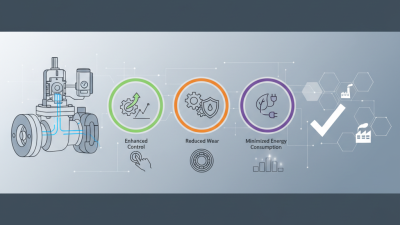
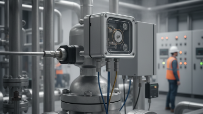
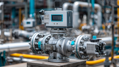
A control valve may receive the correct signal and still fail to deliver the required flow. Friction, pressure differences, stem resistance, and changing process conditions can disturb its movement. A valve positioner helps correct that gap. It compares the requested valve position with the actual stem or shaft position. Then, it adjusts the actuator’s air pressure until both positions closely agree.
Greg McMillan, a respected process-control author and engineer, describes the practical purpose this way: “A valve positioner makes the valve go where the controller tells it to go.” The wording is simple. The engineering is not.
Inside a typical pneumatic system, the controller sends a 4–20 mA signal to an I/P converter. That converter produces a proportional pneumatic signal. The valve positioner then uses feedback from a linkage, rotary sensor, or stem-mounted sensor. It increases or reduces actuator pressure as needed. This response can overcome packing friction and improve positioning accuracy. It can also support split-range control, quick stroking, and diagnostic monitoring.
Yet this explanation is incomplete. Real plants are messier. A loose linkage can create false feedback. Poor calibration can make a stable loop hunt around its target. Incorrect fail-open or fail-closed settings can also create serious operational risks. Understanding how a valve positioner works therefore requires more than memorizing its signal path. It requires examining the actuator, valve trim, process pressure, air quality, and actual field behavior. That practical view makes troubleshooting faster and equipment selection more reliable.
What Is a Valve Positioner and How Does It Work?
A valve positioner is a feedback controller mounted on a control valve actuator. It compares the requested position with actual stem or shaft movement. The device then adjusts actuator pressure until both signals match. It is feedback, not decoration. A small error matters.
The purpose is practical: improve positioning accuracy, reduce hysteresis, and compensate for friction or changing process pressure. IEC 60534 defines the control valve framework, including terminology, sizing, testing, and performance methods. IEC 60534-6-1 covers mounting interfaces for linear valves, while IEC 60534-6-2 addresses rotary valve assemblies. These documents describe scope and test methods. They do not automatically certify every positioner installation.
Pneumatic systems deserve attention. The U.S. Department of Energy’s Improving Compressed Air System Performance guide estimates that leaks can waste 20–30% of compressor output. A poorly adjusted positioner can add unnecessary air consumption through constant correction. Field calibration is less tidy than classroom diagrams suggest. Linkage wear, supply pressure variation, and dirty instrument air can distort feedback. That assumption is convenient, but incomplete. Technicians should verify travel at several command points, inspect tubing, and record supply pressure. The IEC framework helps define performance, yet actual reliability still depends on installation quality and disciplined maintenance.
Ideal 4–20 mA command signal versus calibrated valve stem position
A valve positioner compares the control signal with feedback from the valve stem or shaft, then adjusts the actuator air pressure to reduce the position error. The chart shows the standard linear relationship used for an ideal 4–20 mA control signal: 4 mA represents 0% commanded travel, while 20 mA represents 100%. Actual valve behavior can vary because of calibration, actuator characteristics, friction, hysteresis, and process conditions.
IEC 60534 provides terminology, requirements, and test-related scope for industrial-process control valves; the positioner is one component commonly used to improve valve positioning accuracy and response.
What Is a Valve Positioner and How Does It Work?
A valve positioner converts a 4–20 mA command into controlled valve movement. In a typical setup, 4 mA represents 0% travel, while 20 mA represents 100% travel. A 12 mA signal usually requests 50% travel. The positioner reads this electrical signal and compares it with feedback from the valve stem or rotary shaft. It then adjusts pneumatic pressure until the measured position matches the requested position.
The process is continuous. If friction prevents the stem from reaching its target, the positioner increases or releases air pressure. A small actuator may move within seconds, while a large actuator responds more slowly. During commissioning, technicians verify zero, span, travel direction, and signal response with a calibrated meter. Small errors matter. A loose feedback arm can create unstable movement or an incorrect position indication.
However, 50% travel does not always produce 50% flow. The valve’s internal trim and piping conditions affect flow capacity. That assumption is convenient, but not always true. In field service, I would also check supply pressure, air leaks, linkage alignment, and signal wiring. A perfect current signal cannot correct a sticking valve. Signal failure behavior must be configured carefully, because the valve may move open, close, or remain in place. Calibration is rarely a one-time task; temperature, vibration, and wear can change performance over time.
A valve positioner converts a pneumatic control signal into accurate valve movement. In the common 3–15 psi range, 3 psi represents the closed position, while 15 psi represents full travel. At 9 psi, a correctly calibrated valve should reach about 50% travel. The positioner compares this input with stem feedback, then adjusts air pressure inside the actuator. More air pressure moves the diaphragm or piston against a spring or opposing air chamber.
The response is not always perfectly linear. Friction, packing resistance, spring stiffness, air volume, and supply pressure can change the result. A positioner compensates for some of these effects, especially when the valve operates near a narrow opening. It may also improve response during pressure changes, although poor sizing still creates sluggish movement. Calibration matters more than many users expect.
The U.S. Department of Energy reports that compressed-air leaks can waste 20–30% of compressor output, according to its compressed-air system guidance. That loss can reduce actuator performance and increase operating costs. A practical check includes measuring signal pressure at the positioner, confirming clean instrument air, and comparing commanded travel with actual stem travel. The simple 3–15 psi rule helps, but it is not the whole truth. Field conditions often expose that weakness.
A valve positioner converts a control signal into accurate valve movement. It compares the demanded position with real stem or shaft travel. A feedback sensor reports the actual position continuously. The positioner then adjusts actuator pressure until both values agree.
Across 0–100% travel, calibration defines the relationship between signal and movement. A common setup uses 4 mA for 0% and 20 mA for 100%. The technician checks several points, including 25%, 50%, and 75%. Small errors become visible near the seat or at full opening. Mechanical friction can also create different results during opening and closing. That is easy to overlook.
Split-range control divides one signal between two valves. For example, one valve may operate from 4–12 mA, covering 0–100% of its travel. A second valve may respond from 12–20 mA across its own 0–100% travel. This arrangement can stage heating, cooling, pressure reduction, or flow control.
The transition point needs careful adjustment. Too much overlap may cause both valves to move unnecessarily. Too much separation may create a dead zone.
Field calibration should include supply pressure, linkage alignment, signal accuracy, and actual process response. A positioner can show perfect feedback while the process still behaves poorly. Piping restrictions, sticky packing, or an incorrectly sized valve may be the real cause. Testing only at mid-travel is a weak habit. Test the extremes. Recheck after temperature changes.
A valve positioner converts a control signal into precise actuator movement. It compares the requested position with the valve stem’s actual position. The device then adjusts air pressure to correct the difference. In practice, this prevents sluggish travel, overshoot, and unstable throttling. Even a small feedback linkage error can affect process control.
Digital positioners commonly use HART communication over the existing 4–20 mA loop. The analog signal still controls the valve, while HART carries configuration and diagnostic data. Technicians can check travel deviation, cycle counts, supply pressure, and response time from a handheld interface. These details reveal problems before a valve stops responding. A rising cycle count may indicate friction or process instability. Diagnostics are useful, not magical. Poor calibration can produce convincing but misleading data.
Fail-safe behavior requires careful engineering. On signal loss, power failure, or low instrument air, the positioner may drive the valve open, closed, or hold its last position. The correct choice depends on the process hazard and actuator design. Spring direction, air volume, and shutdown requirements must agree. A fail-safe setting is not automatically safe. During commissioning, technicians should simulate each failure condition and observe the actual valve movement. This step is sometimes rushed. That is a mistake. A positioner can report healthy electronics while a sticky valve remains dangerous. Deathband settings also deserve review, because excessive tolerance can hide small but important control errors.
| Data Dimension | Conventional Pneumatic Positioner | Analog Electro-Pneumatic Positioner | Digital Positioner with HART Communication |
|---|---|---|---|
| Primary Function | Uses a pneumatic control signal and mechanical feedback to position a valve actuator. | Converts a standard electrical current signal into pneumatic actuator pressure while using mechanical feedback. | Uses a microprocessor to compare the input command with valve-stem or shaft position and continuously correct the actuator output. |
| Typical Command Signal | 3–15 psi pneumatic signal is commonly used. | 4–20 mA DC input is commonly used. | 4–20 mA DC signal with digital HART communication superimposed on the analog signal. |
| Typical Output Pressure | Usually proportional to the pneumatic input and sized for the actuator. | Generally regulated to match the required actuator supply and control range. | Electronically modulated pneumatic output, commonly supporting actuator supply pressures up to approximately 6–7 bar (87–102 psi), depending on configuration. |
| Operating Principle | A force-balance or motion-balance mechanism adjusts air pressure according to the difference between command and valve position. | An electromagnetic force motor or torque motor controls a pneumatic relay based on the input current. | A position sensor measures actual travel; the microprocessor calculates position error and adjusts a pneumatic relay or spool valve. |
| Valve Position Feedback | Mechanical linkage, cam, or lever feedback. | Mechanical linkage or rotary feedback mechanism. | Non-contact magnetic, Hall-effect, or conductive position sensing is commonly available; exact sensor type depends on design. |
| Typical Positioning Accuracy | Approximately ±1–2% of span, depending on linkage, calibration, and operating conditions. | Approximately ±0.5–1% of span in a properly calibrated installation. | Often approximately ±0.1–0.5% of span, depending on the actuator, valve, sensor, calibration, and application. |
| Response and Control | Simple and fast, but adjustment is affected by mechanical wear and pneumatic characteristics. | Provides continuous analog control with limited configuration capability. | Uses configurable control algorithms, damping, sensitivity, and travel limits to optimize response and stability. |
| HART Communication | Not normally available | Not normally available | Available on compatible models; supports digital communication over the 4–20 mA loop. |
| Configuration Parameters | Typically adjusted mechanically using zero, span, range, and gain controls. | Usually configured through mechanical adjustments and basic electrical calibration. | Digital configuration may include input range, travel characterization, control response, limits, tuning, alerts, and calibration settings. |
| Auto-Calibration | Generally unavailable | Available on some designs | Commonly available; the positioner can automatically determine travel limits and tune control parameters. |
| Valve Signature Testing | Not normally available | Not normally available | May be available to record friction, seating behavior, travel response, and actuator performance. |
| Diagnostic Functions | Basic visual inspection and mechanical performance checks. | Input-current monitoring and basic calibration checks may be available. | Common diagnostics include travel deviation, cycle count, actuator pressure, supply pressure, friction, temperature, calibration status, and sensor faults. |
| Predictive Maintenance | Limited; mainly based on manual inspection and operating symptoms. | Limited or application-dependent. | Supported when diagnostic data is trended to identify increasing friction, air leakage, sticking, or abnormal valve travel. |
| Fail-Safe Behavior | Determined mainly by actuator type, spring arrangement, and pneumatic design. | Can be configured through actuator spring action and air-supply design. | May support fail-open, fail-closed, or fail-in-place behavior, but the actual result depends on actuator design, air supply, output configuration, and safety settings. |
| Loss of Input Signal | Response depends on the pneumatic circuit and actuator spring action. | May drive the output toward a configured pneumatic state or allow the actuator to move according to its spring return. | Can be configured to exhaust, hold, or drive the actuator output toward a defined state, subject to the selected hardware and safety configuration. |
| Loss of Instrument Air | Usually causes the actuator to move according to its spring-return or double-acting fail-action design. | Usually causes the actuator to move according to its spring-return or air-failure design. | Normally follows the actuator’s mechanical fail action; a positioner cannot guarantee a fail state if the actuator and air circuit are not designed for it. |
| Air Consumption | May be relatively high because pneumatic mechanisms can continuously bleed air during operation. | Moderate to high, depending on relay design and actuator demand. | Often lower in steady-state service because the output is controlled electronically and pneumatic consumption can be reduced by efficient relay designs. |
| Typical Enclosure Protection | Commonly available in weather-resistant industrial enclosures. | Commonly available in weather-resistant industrial enclosures. | Industrial models are commonly offered with dust and water protection ratings such as IP65 or IP66; the actual rating must be verified for the selected device. |
| Hazardous-Area Compatibility | May be suitable because it contains no electrical electronics, subject to applicable certification requirements. | Available in intrinsically safe, explosion-protected, or other certified versions depending on the design. | Available in certified versions for hazardous areas, but installation must comply with the specific approval, wiring method, and barrier requirements. |
| Common Applications | Basic process control, utility systems, and installations where simplicity is the main requirement. | General industrial control loops using conventional 4–20 mA systems. | Process plants requiring accurate control, remote configuration, condition monitoring, reduced maintenance, or integration with asset-management systems. |
| Main Advantages | Simple construction, no electrical power requirement, and straightforward field servicing. | Compatible with standard analog control systems and relatively easy to integrate. | Improved accuracy, automatic calibration, advanced diagnostics, remote setup, reduced mechanical adjustment, and access to operating data. |
| Main Limitations | Limited diagnostics, mechanical wear, manual calibration, and potentially higher air consumption. | Limited digital communication and fewer predictive-maintenance functions. | Higher initial complexity, dependence on correct configuration, need for electrical power, and possible compatibility requirements for communication tools. |
| Recommended Commissioning Checks | Verify supply pressure, signal range, linkage alignment, zero, span, and actuator travel. | Verify loop polarity, input range, air supply, calibration, linkage, and fail action. | Verify wiring and loop resistance, HART communication, sensor travel, air supply, actuator sizing, auto-calibration results, travel limits, alarms, and fail-safe action. |
Note: Performance ranges and fail-safe behavior are representative engineering values. Actual specifications depend on the positioner design, actuator, valve geometry, air supply, certification, and application conditions.
1272 Speers Rd Unit 4
Oakville ON Canada L6L 2X4
©Copyright 2020 Gosco Valves. All rights reserved.