Selecting the right hydraulic valve can determine whether a system runs smoothly or struggles under pressure. A valve controls fluid direction, pressure, and flow, so a small mismatch can create serious operating problems. During equipment inspections, technicians often find symptoms such as slow actuators, overheating oil, or sudden pressure drops. These issues may begin with an unsuitable hydraulic valve.
Performance data should guide the decision. Review the required flow rate, maximum pressure, response speed, connection size, and fluid type. Check the manufacturer’s technical documentation carefully. Real working conditions matter too. A valve rated for clean laboratory oil may perform poorly in a dusty construction environment. Contamination can damage sensitive internal parts. Temperature changes can also affect seals and response.
The cheapest option is not always economical. That assumption is tempting, but incomplete. A low-cost valve may increase downtime, maintenance visits, and energy loss. Experienced engineers compare total operating cost, not only the purchase price. They also consider installation space, spare-part availability, service access, and operator safety.
Every system has compromises.
For example, a fast proportional valve may improve control but require cleaner fluid and better electrical tuning. A simple directional valve may be more reliable for basic lifting equipment. The best choice depends on verified system requirements, not attractive product claims. Careful selection supports stable pressure, predictable motion, and longer component life. Still, no recommendation should be treated as universal. Field measurements, supplier guidance, and practical testing remain essential before final approval.
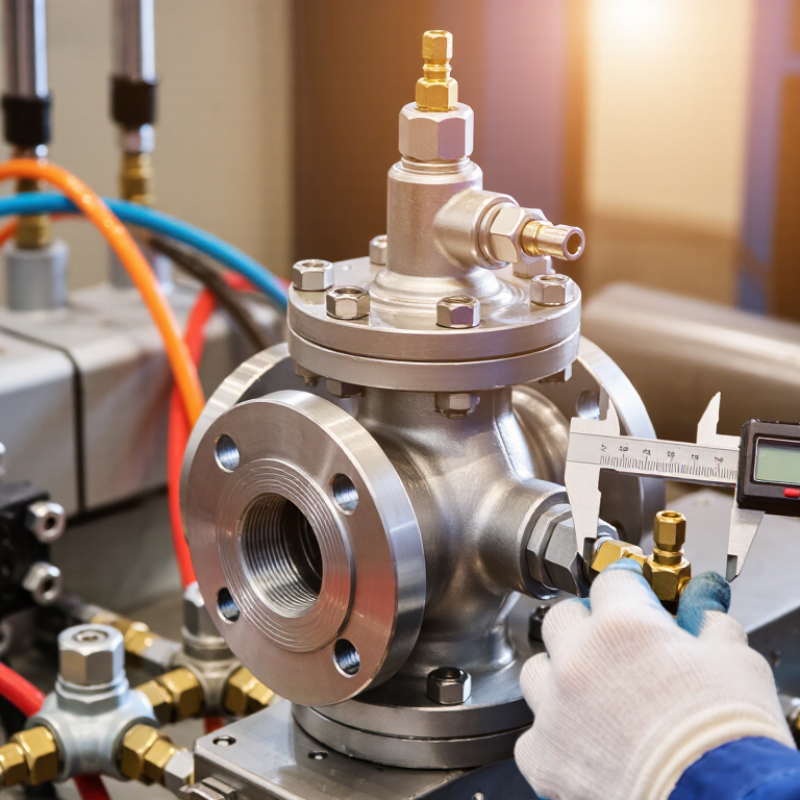
Why Choose the Right Hydraulic Valve for Your System?
A hydraulic valve directs, controls, or stops pressurized fluid inside a power system. It manages how oil reaches cylinders, motors, and other actuators. Directional valves determine movement, while flow valves adjust speed and pressure valves limit force. Each function affects machine response, energy use, and operating safety. In field service, I have seen a small valve mismatch create slow movement and unwanted heat. The symptoms were easy to miss.
Pressure matters.
Choosing a valve requires more than matching pipe size. Engineers should check flow rate, pressure range, fluid type, response time, and mounting conditions. A valve that works well at low pressure may perform poorly near its limit. Contamination can also damage precise internal parts, even when installation appears correct. I once underestimated temperature changes during equipment testing, and the measured response became inconsistent. That mistake reinforced the value of testing under real operating conditions. Clear documentation helps technicians identify ports, settings, and maintenance needs. It also reduces adjustment errors during repairs. The right hydraulic valve gives the system controlled motion, predictable force, and dependable protection against excessive pressure.
| Valve Type | Primary Function | How It Controls Fluid Power | Typical Applications | Key Selection Factors | Main Benefit | Common Limitation |
|---|---|---|---|---|---|---|
| Directional Control Valve | Starts, stops, or redirects hydraulic fluid. | Changes the flow path between the pump, actuator, reservoir, and return line. | Hydraulic cylinders, hydraulic motors, lifting equipment, and machine tools. | Number of ports and positions, flow capacity, pressure rating, actuation method, and response time. | Provides reliable control of actuator direction and movement. | Incorrect port configuration can cause unexpected actuator motion or loss of control. |
| Pressure Relief Valve | Limits maximum system pressure. | Opens when pressure reaches its setting and diverts excess flow back to the tank or a low-pressure circuit. | Nearly all pressurized hydraulic systems, including power units and mobile machinery. | Pressure setting range, flow-handling capacity, adjustment stability, and response characteristics. | Protects pumps, actuators, piping, and seals from excessive pressure. | Continuous relief flow can generate heat and waste energy. |
| Pressure-Reducing Valve | Maintains lower pressure in a branch circuit. | Restricts inlet flow as downstream pressure approaches the preset value. | Clamping circuits, pilot controls, tool circuits, and systems with different pressure zones. | Required downstream pressure, flow demand, pressure differential, and sensitivity to load changes. | Allows low-pressure components to operate safely within a higher-pressure system. | It cannot increase downstream pressure when the available inlet pressure is too low. |
| Flow-Control Valve | Regulates actuator speed. | Controls the volume of fluid entering or leaving an actuator, often using an adjustable restriction. | Controlled cylinder extension, motor speed regulation, and sequencing operations. | Required flow range, pressure-compensation needs, metering direction, and heat generation. | Offers a practical way to control operating speed. | Non-compensated designs may allow speed to change when the load or pressure varies. |
| Check Valve | Allows flow in one direction only. | A spring-loaded or pilot-operated poppet or spool opens in the permitted direction and blocks reverse flow. | Load holding, pump outlet protection, hydraulic circuits, and line isolation. | Cracking pressure, reverse leakage, flow capacity, pressure rating, and response time. | Prevents reverse flow and helps maintain hydraulic circuit stability. | Excessive cracking pressure can reduce efficiency and available actuator force. |
| Counterbalance Valve | Controls overrunning loads and prevents uncontrolled descent. | Maintains back pressure at an actuator outlet and opens in a controlled manner when pilot pressure is applied. | Boom lifts, winches, vertical cylinders, and suspended loads. | Load mass, maximum pressure, pilot ratio, flow rate, and required lowering speed. | Improves load holding and helps prevent runaway movement. | Improper adjustment can cause instability, pressure spikes, or excess heat. |
| Sequence Valve | Activates a secondary hydraulic function after a preset pressure is reached. | Remains closed until the primary actuator reaches the selected pressure level, then opens the next circuit. | Multi-step clamping, drilling, pressing, and automated machine cycles. | Sequence pressure, flow requirement, cycle timing, leakage tolerance, and load interaction. | Coordinates multiple hydraulic operations without separate electrical control for every step. | Pressure-based sequencing may be affected by load changes and friction. |
| Proportional Valve | Provides variable control of flow or pressure. | Uses an electrically controlled solenoid to vary spool position in proportion to an input signal. | Mobile equipment, material handling, industrial automation, and motion-control systems. | Command signal, hysteresis, repeatability, flow range, electronics, and contamination control. | Provides smoother and more precise control than basic on-off valves. | Requires suitable electrical control, calibration, and cleaner fluid than simple manual valves. |
| Servo Valve | Provides highly precise flow or position control. | Uses a sensitive electrohydraulic control stage to make rapid, continuous adjustments. | Test equipment, aerospace systems, simulation systems, and precision manufacturing. | Dynamic response, filtration level, null stability, rated flow, and control-loop requirements. | Delivers excellent accuracy and fast dynamic response. | High sensitivity to contamination, greater cost, and more demanding maintenance requirements. |
| Cartridge Valve | Performs directional, pressure, or flow-control functions in a compact manifold. | Uses a cartridge element installed in a machined cavity, often combined with a cover or pilot control. | Compact power units, presses, injection machinery, and high-flow systems. | Manifold design, cavity standard, flow capacity, leakage requirement, and service access. | Supports high flow rates with compact installation and reduced external piping. | Diagnosis and replacement can be more difficult without suitable manifold documentation. |
Selection note: Confirm the valve's rated pressure, rated flow, fluid compatibility, temperature range, installation orientation, response requirements, and contamination-control needs against the actual system conditions. Published values vary by design and application.




©Copyright 2020 Gosco Valves. All rights reserved.