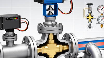
How to Choose a Temperature Control Valve?
Choosing a temperature control valve is not a catalog exercise. It is a process decision. The IEA’s Energy Efficiency 2023 report estimates that industry accounts for about 37% of global energy use, making stable thermal control an important efficiency consideration. Yet a valve that looks correct on a piping diagram can still hunt, leak, or respond slowly when real flow conditions change. Small details matter.
Start with the process fluid, temperature range, pressure drop, and minimum and maximum flow. Then consider the required fail position, actuator response, leakage class, and available utilities. A steam line with noisy pressure swings needs different attention from a clean-water loop serving a jacketed tank. Check the valve’s controllability across its working range, not only its nominal size. Oversizing is common—and it can make low-load control frustrating.
Béla G. Lipták, a process-control author and editor of the Instrument Engineers’ Handbook, has written extensively about matching control equipment to process behavior. A concise paraphrase of that engineering principle is: “Choose for the process, not the pipe.” Treat it as a reminder, not a verbatim quotation. Emerson’s Control Valve Handbook also provides practical guidance on valve sizing, characteristics, and actuator selection. Use manufacturer sizing tools, then verify assumptions with operating data or a qualified engineer. A final review should test the actual fluid properties and worst-case conditions. That step is easy to skip. Don’t. A well-chosen temperature control valve should deliver stable control throughout the operating range—not merely fit the connection.
Define the Temperature Control Requirements
How to Choose a Temperature Control Valve?
Define the Temperature Control Requirements
Before selecting a temperature control valve, define what the process must hold—not just its nominal setpoint. Record normal, minimum, and maximum inlet temperatures, outlet targets, flow rates, and pressure. Include the fluid and its properties; hot water, steam, and viscous liquids behave differently. Small details matter. A 5°C overshoot may be harmless in one process but damage a temperature-sensitive product in another.
Describe how conditions change during operation. Note startup time, peak demand, batch changes, and the smallest expected load. Specify the acceptable temperature band and how quickly the system must recover after a disturbance. The U.S. Department of Energy’s 2022 Industrial Decarbonization Roadmap reports that industry produced about 30% of U.S. energy-related CO2 emissions in 2020. That figure is not a valve-sizing rule; it does underline why unnecessary heating and cooling deserve attention.
Also define the installation and failure requirements. Identify available actuator power, sensor location, pipe orientation, and the valve’s required position if power or control signals fail. Confirm whether the valve must modulate smoothly at low flow, where oversized valves can cause unstable temperature swings. No specification is perfect at first. Review real operating data where possible, and mark assumptions clearly; guessed peak loads can lead to poor control.
Compare Temperature Control Valve Types
How to Choose a Temperature Control Valve?
Compare Temperature Control Valve Types
Self-operated thermostatic valves sense temperature through an internal element and adjust flow without an external power supply. They suit simple heating or cooling circuits, such as maintaining hot-water temperature in a small tank. No wiring needed. Their response and adjustment range may be limited, so check the required accuracy and operating conditions.
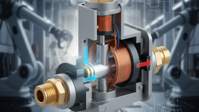
Electric control valves use a temperature sensor, controller, and powered actuator. They allow adjustable setpoints and can respond well to changing loads, but require a reliable power supply and compatible controls. Pneumatic valves use compressed air to move the actuator. They can fit plants with existing instrument-air systems, though air quality and pressure need attention. Neither type is automatically better; the control system and maintenance capacity matter.
Also compare two-way and three-way designs. A two-way valve throttles flow through one path, while a three-way valve mixes or diverts flow between paths. Three-way valves can simplify some bypass arrangements, but piping and load conditions affect performance. This distinction describes flow routing, not the actuator type. Before choosing, check fluid compatibility, pressure drop, temperature range, connection size, and fail position. A valve that looks right on paper may still respond poorly if it is oversized. That detail is easy to miss.
How to Choose a Temperature Control Valve? Compare Valve Flow Characteristics
Compare how valve travel affects flow capacity. These curves show inherent flow characteristics, not measured performance of specific valves.
A linear characteristic provides an approximately proportional change in flow capacity with travel. An equal-percentage characteristic produces progressively larger flow changes as the valve opens; the curve shown uses an illustrative 50:1 rangeability. Choose a characteristic to suit the system and control requirements. Self-operated, pneumatic, and electric describe actuation methods and can be paired with different valve designs.
Match Valve Materials, Pressure, and Flow Ratings
A temperature control valve performs reliably only when its materials, pressure rating, and flow capacity suit the system. Start with the fluid: water, glycol mixtures, steam, and process chemicals can affect the body, trim, and seals differently. Check the temperature range, too. A seal may handle pressure but still harden or swell under heat. For corrosive or abrasive fluids, confirm compatibility at the actual concentration and temperature, not from a generic chart alone.
Tips: Record inlet and outlet pressures, flow rate, and fluid temperature during normal operation. Include startup and shutdown conditions. Compare these readings with the valve’s pressure rating and flow coefficient. An undersized valve can restrict flow; an oversized one may cycle unevenly and cause temperature swings. Avoid guessing at the required margin.
Small details matter. A valve installed far from its sensor may respond slowly, even when its ratings look correct. Check the control signal, actuator range, pipe size, and installation orientation against system requirements. If operating data is incomplete, measure it before ordering. Nominal pipe size alone is not enough; differential pressure is easy to overlook, and worth checking before commissioning.
Check Actuator, Sensor, and System Compatibility
A temperature control valve works as part of a loop, not in isolation. Match the actuator to the controller’s output, such as a 4–20 mA signal, a switching signal, or pneumatic pressure. Check supply voltage, available air pressure, mounting arrangement, and required travel. The valve may fit the pipe perfectly and still respond poorly. Small details matter.
Confirm that the sensor measures the temperature that actually needs control. A sensor placed far from the valve, or inside a poorly fitted thermowell, can report changes too slowly. That delay may cause temperature swings. Check the sensor’s range, response time, and installation point against the process conditions. Not just the connection. The control system’s input type and calibration must also match the sensor.
Then compare the valve’s materials, pressure rating, flow capacity, and temperature limits with the fluid and operating conditions. A valve sized only by pipe diameter may be oversized, leading to unstable control at low flow. Review the manufacturer’s technical data and have a qualified engineer verify sizing when conditions are uncertain. During commissioning, test the full loop: change the setpoint, observe sensor response, and confirm actuator movement and fail position. One overlooked mismatch can be difficult to diagnose later.
Evaluate Installation, Maintenance, and Safety Needs
A temperature control valve must fit the real installation, not just the process diagram. Check the pipe size, connection type, flow direction, and available clearance before choosing a model. Measure around nearby insulation, supports, and instruments. Small details matter. In practice, drawings can make service space look generous; installed pipework often disagrees. Confirm the valve can be reached without dismantling unrelated equipment.
Maintenance needs should shape the choice, too. Ask whether seals, trim, or actuators can be inspected and replaced on site. A removable actuator may save time when access is tight. Check the expected service interval against fluid quality, operating temperature, and cycling frequency. Dirty or scaling fluids can increase sticking and wear, so a valve that works well at commissioning may need more attention later. That assumption is easy to miss.
Safety depends on the whole control loop, not the valve alone. Verify the pressure and temperature ratings, and confirm the selected failure position suits the process. Consider what happens if power, instrument air, or the temperature sensor fails. Provide isolation where maintenance requires it, and ensure the system can be made safe before work begins. The correct response varies by process; do not treat “fail open” or “fail closed” as a universal rule. Check the installation details with a qualified process or controls engineer.