Selecting a spring return actuator is a safety decision, not merely a purchasing task. Valve size, torque, air pressure, temperature, and failure position must work together. A small mismatch can leave a butterfly valve partially closed during a shutdown.
Industry data supports careful selection. MarketsandMarkets’ Industrial Automation Market report identifies process efficiency, safety, and remote operation as major adoption drivers. Fortune Business Insights’ Industrial Valves Market report also connects valve demand with water treatment, chemical processing, energy, and oil and gas facilities. These sectors often require dependable fail-safe movement.
Béla G. Lipták, editor of the Instrument Engineers’ Handbook, states, “The control valve is the final control element in most process control loops.” That observation applies directly to actuator choice. The actuator is where a control signal becomes physical movement. Its return spring must move the valve reliably when air or power disappears.
This guide presents seven practical tips for choosing a spring return actuator. It examines fail-open and fail-closed operation, breakaway torque, safety margin, cycle frequency, environmental protection, mounting standards, and maintenance access. Each point connects specifications with conditions found on real equipment, including cold outdoor lines, humid pump rooms, and dusty processing areas.
Numbers can mislead.
A generous torque rating is not automatically better. Oversizing may increase cost, wear, and response time. Undersizing is more dangerous. Manufacturer charts also deserve scrutiny, especially when pressure drops, corrosion, or hardened seals are present. The right choice comes from verified valve data, documented operating conditions, and a little healthy doubt.
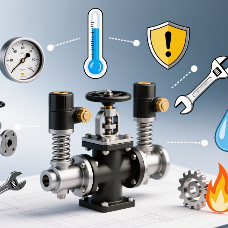
For a 90° spring-return valve, actuator selection begins with accurate torque data.
Tip one: identify breakaway, running, and seating torque separately. Breakaway torque may rise after long periods without movement.
Tip two: use the valve’s worst-case torque, not its average value. Dirty media, dry seals, and low temperatures can change performance.
Tip three: apply a realistic safety margin. A common engineering range is 25% to 50% above the highest required torque. The exact margin should reflect process risk and verified test data.
Tip four: compare the actuator spring torque with valve demand at every angle. Spring output decreases during the return stroke. That detail is often missed. I have seen selections pass bench checks yet fail near the final seating position.
Tip five: define the fail position clearly, then confirm the spring direction matches the process hazard assessment.
Tip six: check temperature, corrosion, cycling frequency, and available air pressure. These conditions affect both friction and actuator output.
Tip seven: test the complete valve assembly, not the actuator alone. Record opening time, closing time, and final seating torque.
Small errors matter. One practical improvement is repeating the test after thermal cycling, because seals can behave differently afterward. Selection should also reference current project specifications, maintenance experience, and applicable engineering standards.
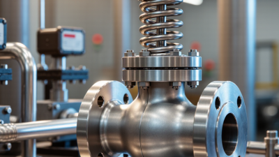
Match the actuator output with ISO 5211 valve-mounting dimensions before comparing spring packages. ISO 5211 standardizes flange patterns and drive interfaces, but it does not define the valve’s operating torque.
For example, an F07 mounting flange uses a 70 mm nominal interface, while F10 uses 102 mm.
The actuator must fit the flange and square drive without adapters, play, or forced alignment.
Measure the valve shaft and mounting face in the field. Drawings are useful, but they are not always current.
Check breakaway, running, and seating torque separately. Then add a realistic safety margin, commonly 25–30%, without hiding poor data. Spring return units can deliver different torque values during their stroke, so compare the complete torque curve.
A 2023 U.S. Department of Energy guide notes that pumping systems may consume 25–50% of industrial electricity; inefficient valve positioning can increase that burden through pressure loss. Compressed-air consumption also matters.
A smaller actuator may appear economical, yet fail during cold starts or sticky-seat conditions. I have seen this mistake. It was expensive.
Select the spring direction carefully: fail-open and fail-closed are not interchangeable. Confirm supply pressure, corrosion exposure, cycle frequency, and accessory load.
Independent test reports should show output torque, spring decay, operating temperature, and ISO 5211 compatibility.
If the available valve torque data seems unusually clean, question it. Real installations are rarely perfect.
Selecting fail-open or fail-close action is a process safety decision, not a simple actuator preference. When air pressure or power disappears, the valve must move toward the safer condition. Fail-close may stop fuel, steam, or chemical feed. Fail-open may release pressure, maintain cooling, or prevent equipment damage. The correct choice depends on the hazard review.
Study the process response, not just the valve position. Ask what happens during fire, instrument failure, blocked discharge, or loss of utility supply. A closed valve can contain danger, but it can also trap expanding liquid. An open valve can protect equipment, yet it may increase emissions or feed a hazard. That assumption fails. Review pressure, temperature, flow direction, and downstream capacity with qualified process and safety engineers.
Check spring force across the full stroke. Friction, high differential pressure, and cold conditions can change actuator performance. Confirm the fail position during commissioning, including low air pressure and power loss. Record closing or opening time, travel indication, and manual reset behavior. Test it cold. Then test it under realistic operating conditions. Periodic proof testing should reflect the safety function and identify sticking, corrosion, or degraded seals. In field reviews, teams sometimes choose fail-close automatically because it feels safer. That shortcut needs challenge. The safest action may change with operating mode, inventory, and emergency response procedures. Calibration records, cause-and-effect diagrams, and maintenance access also deserve careful review.
An IP rating is a test result, not a promise of universal weather resistance. IEC 60529:2013 defines the first digit for solids and the second digit for water. For example, an IP65 enclosure withstands dust ingress testing and a 12.5-litre-per-minute water jet. The water test lasts at least three minutes per square metre, according to IEC 60529 test conditions. Check the complete code. IP67 adds temporary immersion at one metre for 30 minutes, but it does not automatically replace IP65 jet protection.
Temperature deserves equal attention. A spring return actuator may operate near a hot valve, inside a cold plant room, or under direct sunlight. Compare the stated operating range with measured ambient conditions, not seasonal averages. IEC 60068-2-1 and IEC 60068-2-2 provide recognized cold and dry-heat test methods, but they do not establish one universal actuator temperature limit. That limit comes from the equipment documentation and its tested materials.
Look for separate values for operation, storage, humidity, and cycling. A recurring field mistake is treating a short exposure rating as continuous service approval. Another is ignoring heat from nearby pipes. Measure the enclosure surface, then allow a practical margin.
Be cautious here. Installation orientation, cable glands, condensation, and aging seals can reduce real protection. Even a certified IP rating can disappoint when the installation is poorly sealed.
Choosing a spring return actuator starts at the valve, not the catalog. Confirm the valve’s breakaway and running torque under real operating conditions. Then match the actuator’s output torque in both directions. Spring torque changes during the stroke. NAMUR VDI/VDE 3845 defines important mounting dimensions and shaft interfaces. Verify the correct interface pattern before ordering accessories. A small mismatch can create alignment problems, leakage risks, or delayed installation.
Check every accessory against the same interface standard. Solenoid valves, position monitors, switch boxes, and manual overrides should mount without improvised brackets. Confirm shaft height, bolt spacing, drive shape, and available clearance. Ask for dimensional drawings, not only product images. Images can mislead. Review the required fail position, air pressure range, ambient temperature, and enclosure protection. These details often affect accessory selection more than nominal actuator size.
Cycle-life requirements need a written duty profile. Record daily cycles, valve torque changes, switching speed, media temperature, and emergency closures. Request test data that reflects the complete assembly, including springs, seals, bearings, and accessories. A high cycle count under clean laboratory conditions may not represent field service. Measure it. Include corrosion exposure and pressure fluctuations in the evaluation. I have seen reliable calculations fail because the valve became harder to move after months of service. Add a practical torque margin, but avoid excessive oversizing, which can increase cost and stress. Recheck the assumptions before approval.
1272 Speers Rd Unit 4
Oakville ON Canada L6L 2X4
©Copyright 2020 Gosco Valves. All rights reserved.