A hydraulic valve may look like a compact metal block, but its passages determine where oil travels, how much pressure builds, and how smoothly a machine moves. In a loader, pressurized fluid can raise a bucket; in a factory press, it can hold a ram steady. What Are the Types of Hydraulic Valves? The answer depends on the job each valve performs, not just its shape. Directional valves route flow. Pressure-control valves limit or maintain pressure. Flow-control valves adjust speed. Some designs combine functions, which can make labels less tidy in real circuits.
Hydraulic-control author John Watton’s work offers a useful principle, paraphrased here rather than quoted verbatim: “Choose a valve by the behavior the circuit needs, then check its operating conditions.” That distinction matters. A valve that works well at one flow rate may respond differently under higher pressure, warmer oil, or contamination. Small parts. Big consequences. This guide examines common valve types, their operating roles, and the details that influence selection, including port arrangement, actuation method, and response characteristics. It also recognizes a practical limitation: categories explain the basics, but they cannot replace checking a real circuit diagram and manufacturer specifications. The goal is a clear starting point for understanding how each hydraulic valve guides fluid—and where its limits begin.
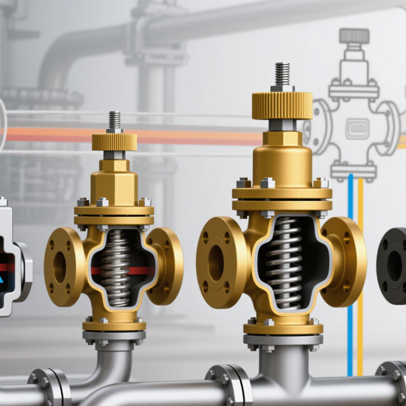
Hydraulic valves are commonly grouped by the job they perform: directing fluid, limiting pressure, regulating flow, or preventing reverse movement. Directional control valves use a spool or poppet to route oil between the pump, actuator, and tank. A four-way valve, for example, can send fluid to one side of a cylinder while returning fluid from the other. Port labels and circuit diagrams matter; a small connection error can make a cylinder move in the wrong direction.
Pressure-control valves manage force and protect components. A relief valve opens when system pressure reaches its set level, often sending oil back to the tank. Flow-control valves adjust actuator speed by restricting flow through an orifice or compensating for pressure changes. Check valves allow fluid to pass one way and block it in the other; pilot-operated versions can release trapped fluid when commanded. These categories can overlap in real circuits. A neat chart can hide that. Temperature, contamination, and installation orientation may affect performance, so technicians should verify settings under operating conditions and consult the equipment’s hydraulic diagram. Even a correctly selected valve may behave differently when the load changes.
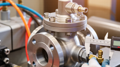
Directional valves are often described by port count and spool positions. A 4/3 valve has four ports and three spool positions. The ports usually connect pressure, tank, and two actuator lines. In neutral, a closed-center spool blocks all four paths; a tandem-center design connects pressure to tank while blocking actuator lines. Small detail, big effect. A cylinder may hold its load, drift, or move unexpectedly if the center condition does not suit the circuit. Engineers should check the schematic against the actual spool, not rely on shorthand alone.
Mounting dimensions matter during replacement. ISO 4401:2005 specifies mounting surfaces for four-port directional valves, including interface dimensions and port locations. Common interface sizes include NG6, often associated with CETOP 3, and NG10, often associated with CETOP 5. These labels help compare footprints, but they do not guarantee equal flow capacity. A published rating depends on pressure drop, fluid viscosity, and test conditions. Check the valve data sheet and the manifold drawing together. A neat drawing can still mislead. Port labels, bolt spacing, cavity depth, and seal position all deserve a physical check before installation. ISO defines the interface; it does not choose the right spool function for a machine.
Common directional-valve configurations compared by the number of ports and spool positions.
How to read it: In a valve designation such as 4/3, the first number is the number of ports (ways) and the second is the number of spool positions. ISO 4401 sizes, such as 03, 05, and 07, specify standardized mounting interfaces; they do not define a valve’s port count or spool positions.
At 210–350 bar, pressure-control valves protect circuits and direct flow according to load conditions. That range equals 21–35 MPa; it is an application range, not a universal rating. A relief valve opens when inlet pressure reaches its setting, sending excess flow back to tank. Set it too high, and hoses or actuators may face damaging pressure. Set it too low, and the machine may stall under load. ISO 4413:2010 requires hydraulic systems to be designed against excessive pressure and identifies pressure-limiting devices as one protective measure. Real settings must also account for pressure spikes, temperature, and component ratings.
Reducing valves maintain lower pressure in a branch, such as a clamping circuit that shares a higher-pressure supply. Sequence valves open after upstream pressure reaches a set threshold, allowing operations to occur in order. Small details matter. A clogged pilot passage or poorly adjusted spring can change response. ISO 10771-1:2015 provides a fatigue-test method for metallic pressure-containing components under fluctuating pressure; it does not certify an entire installed circuit. That distinction is easy to miss. In practice, technicians should verify settings with a calibrated gauge under operating conditions, then record the measured pressure and load. The chosen valve’s rated pressure, flow capacity, and duty cycle still need to match the system.
Flow-control valves meter hydraulic fluid by changing the size of an opening. A spool or needle moves within the valve, creating a narrower or wider passage. This sets the flow rate reaching a cylinder or motor. A small adjustment can noticeably change actuator speed.
For a simple restriction, flow rate follows Q ∝ A√Δp, where A is the opening area and Δp is the pressure drop across it. Increase the opening, and more fluid can pass. Increase the pressure difference, and flow also rises, but by the square root rather than in direct proportion. In real valve calculations, fluid density and the passage’s discharge characteristics matter too. The formula is a useful model, not a complete prediction.
That distinction shows up on the machine. If a load changes, the pressure drop across an ordinary metering valve may change, shifting actuator speed even when the valve opening stays fixed. Pressure-compensated designs help hold flow steadier by maintaining a more consistent pressure drop across the metering edge. They do not erase every variation. Oil temperature, contamination, and wear still affect performance. A warm reservoir can make the same setting feel different. It is easy to overlook.
What Are the Types of Hydraulic Valves?
Check, proportional, and servo valves differ in how they control hydraulic flow. A check valve allows oil to pass in one direction and restricts reverse flow. In an ISO 1219 diagram, its symbol shows the valve’s basic function; spring-loaded versions include an added spring mark. A check valve near a cylinder can help prevent reverse flow, but it should not automatically be treated as a complete load-holding solution. Circuit layout matters.
Proportional valves vary flow or pressure in response to an electrical input. Servo valves use precise control, often with feedback, to adjust flow quickly and accurately. They suit systems that need responsive motion, such as a test rig moving a hydraulic actuator by millimetres. ISO 1219 symbols identify functions and control methods, not every detail of electronics or performance. A diagram cannot show response time, leakage, or contamination tolerance. That gap matters. Selection is not always obvious.
Tips: Read the symbol alongside the circuit notes and valve data. Check the required flow, pressure, response, and oil cleanliness. A small symbol can hide a demanding application.
| Valve Type | Primary Function | Control Method | Typical Response and Control | ISO 1219 Symbol Representation | Common Applications |
|---|---|---|---|---|---|
| Check valve | Allows flow in one direction and prevents or limits reverse flow. | Usually controlled by fluid pressure. A pilot-operated check valve can be opened by pilot pressure to permit reverse flow. | Typically a simple, discrete function: flow is allowed when the opening pressure condition is met; otherwise, reverse flow is blocked. | Shown as a one-way valve function with a closure element and seat. A spring may be included when the valve is spring-loaded; pilot-operated versions include a pilot-control connection. | Load holding, preventing reverse flow, and maintaining pressure in a hydraulic line or actuator. |
| Proportional valve | Continuously varies flow, pressure, or directional control in response to an electrical command. | An electrical signal drives a proportional solenoid, which adjusts the valve element. The command may come from a controller; feedback may be included in the system. | Variable control between operating states. Response and accuracy depend on valve design, electronics, fluid conditions, and whether position or system feedback is used. | Typically uses the relevant ISO 1219 directional, pressure, or flow-control function symbol, together with an actuator representation or annotation indicating proportional electrical control. The symbol describes function and actuation, not a universal performance rating. | Adjustable actuator speed, variable flow or pressure, and machine functions requiring smooth command-based control. |
| Servo valve | Provides precise, dynamically controlled regulation of hydraulic flow or pressure. | An electrical command operates a servo mechanism, commonly within a control system using feedback from a position, pressure, or other sensor. | Designed for fine control and rapid response in suitable systems. Actual bandwidth and accuracy depend on the valve, controller, load, and hydraulic circuit. | Represented by the applicable ISO 1219 valve-function symbol and the appropriate actuation or pilot-control details. Servo behavior is generally clarified with a label or circuit documentation rather than inferred from a single universal symbol. | Closed-loop motion control, test equipment, and applications requiring precise actuator positioning or dynamic response. |
Symbol note: ISO 1219 uses standardized graphical symbols to show hydraulic components and their functions. The exact symbol depends on the valve configuration, ports, operating positions, and actuation method; proportional and servo performance may also require a written designation or circuit documentation.
1272 Speers Rd Unit 4
Oakville ON Canada L6L 2X4
©Copyright 2020 Gosco Valves. All rights reserved.